Continue to Site

Welcome to EDAboard.com

Welcome to our site! EDAboard.com is an international Electronics Discussion Forum focused on EDA software, circuits, schematics, books, theory, papers, asic, pld, 8051, DSP, Network, RF, Analog Design, PCB, Service Manuals... and a whole lot more! To participate you need to register. Registration is free. Click here to register now.

[PIC] Power factor measurement using PIC18f4520

Status
Not open for further replies.
Hi,

@Brian:
I should have read your post #135 more carefully. You gave all the information.
But somehow i missed it.

With U and I at the ADC, then the microcontroller has all information it needs. No need to input averag_power.

Non simultaneous ADC sampling.
The higher the sampling frequency (interleaved U and I) the lower the error.
And the error is known, so it is simple mathematics to compensate it. It is a fixed phase angle.

Klaus

Isn't a 3x3 keypad necessary such that a user can manually enter the apparent power? Does 74LS86 does that instead in analog mode?
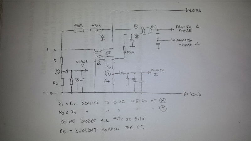
betwixt said that I should enter the two waveforms to XOR, does that mean I take a parallel line from PORTA.0 (the one supposed to be an ADC of voltage) and enter it at pin #1 of the XOR logic gate, and similarly take another parallel line from PORTA.1 (the one supposed to be an ADC of current) and enter it at pin #2 of the XOR logic gate, then take pin #3 of the XOR to PORTA.2 ??

- - - Updated - - -

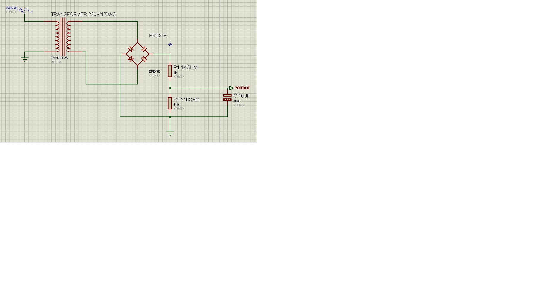
1. measure voltage with one ADC input
2. measure current with a second ADC input.
3. XOR (use a logic gate such as 74LS86 or equivalent) the two waveforms, feed it through a low pass filter and measure the resulting voltage through a third ADC input.

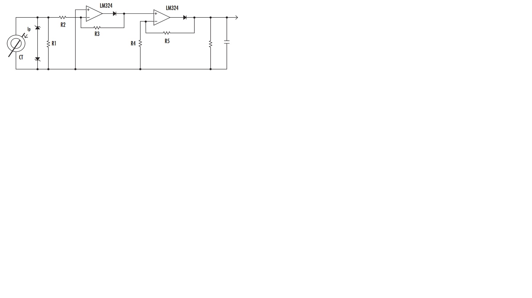
As long as you 'square up' the voltage and current waveforms using an op-amp or comparator before feeding them to the XOR gate, it's output will be a pulse with width equal to the phase difference in the signals. If you filter it to find the average, you get an analog voltage proportional to the phase shift.

It isn't using the zero crossing method at all but it will allow you to measure V, I, apparent power and phase displacement using simple math.

Brian.

Dear Brian,

How to XOR the two wave forms? and what are the specs of the low pass filter? How to know pf from the resulting voltage of the XOR gate?

- - - Updated - - -

* measure voltage and calculate RMS_voltage
* measure current and calculate RMS_current
* multiply RMS_voltage x RMS_current and get apparent_power
* at every maesurement calculate actual_current x actual_voltage and get true_power
* Now just divide true_power / appareant_power and get cos(phi)

getting RMS voltage would take integral calculation as well as square root for that integral, can't the user input the apparent power by using a keypad?
 

@FvM

Ok. I will try your code.

Here I am posting new mikroC Code. There was a problem with the previous code. It was only showing pf value for lagging current. I have fixed it and now it shows pf value for leading and also lagging current but I still feel that there is something wrong in the code because it has to show proper sign (+ / -) when leading or lagging current is detected. I have to use a variable to check which INTx 9INT0 / INT1) occured first and based on that change the sign of the result.

@Khaled Osmani

You can test this attached project in hardware but the two ZCD signals should be as shown in the image.
 

Attachments

  • Mains Monitor 20 ms Timer Interrupt ver3.rar
    126.1 KB · Views: 67
  • pf measurement.png
    pf measurement.png
    112.6 KB · Views: 81

Hello,

If using this current sensor: **broken link removed**

and placing at its two terminals a 1kOhm resistor (instead of its rated burden of 200Ohm) such that when maximum ampere of 10A is detected, its secondary ampere would be 5mA, and with 5mA multiplied with 1kOhm I would have a maximum 5V output.

Can this be considered a way to enter the resultant voltage to PORTA.2 and hence using math know the initial current value?
 

Hi betwixt

Please provide the circuit (interface circuit) for the method of measurement you mentioned. If possible provide Proteus circuit or circuit drawn in mspaint.

Also mention the algorithm for measurement. I will try to write a code for the OP.

- - - Updated - - -

@betwixt

Can I use this Circuit for the method of voltage measurement you mentioned ?

@Khaled Osmani

You have to use a diode after the 1k resistor to convert the AC voltage to DC voltage and this will drop 0.7V across the diode.
 

Attachments

  • voltage measurement.png
    voltage measurement.png
    22.3 KB · Views: 88

Hi,

Please tell me how to calculate apparent power and true power using adc. A sample code would be helpful. You can show it for AVR.
I tried to describe it in post #136.

What is unclear?

Klaus
 

Hello,

Here is the circuit for voltage ADC in:


Here is the circuit for current ADC in:


I just need the specifications of resistors/capacitor of the current ADC in.

Also Please tell how to feed the 74LS86 IC and where to get its inputs/output and what routine should be coded within the PIC to get phase cosine.

the CT ratio is 10A/5mA with datasheet burden of 200Ohms

Thanks
 

Hi betwixt and others

Can OP use this circuit for voltage measurement ? (Considering the method mentioned by betwixt).

@KlausST

I have never done a AC RMS voltage or Current measurement using PIC. I use PIC and I know that you don't use PIC. If possible please provide AC Voltage, Current and PF measurement interface circuit for AVR and also C Code for it. I will port it to PIC for the OP.

- - - Updated - - -

Test this circuit. Use exact resistor values. measure all the voltages and post it here. You have to vary the current from 0 to 10A for your CT primary and it will give 0 to 50 mA at secondary then post just the voltages you get across the output of bridge rectifier and the two resistors for some random values between 0 to 10A. Don't connect it to PIC.

If the voltages vary properly then it can be connected to PIC and used with my code.

The voltage and current measurement circuits that I have provided doesn't work with KlausST's method.

You can't use 1k resistor across the CT's output because 50 mA * 1k = 50V.


@FvM

In the code you posted

Code:
#int_EXT
void ext_isr(void) {
   disable_interrupts(INT_EXT_L2H);
   set_timer1(0);
   clear_interrupt(INT_EXT1);
   enable_interrupts(INT_EXT1_L2H);
}

#int_EXT1
void ext1_isr(void) {
   disable_interrupts(INT_EXT1_L2H);
   timer_value = get_timer1();
   process = 1;
   clear_interrupt(INT_EXT);
   enable_interrupts(INT_EXT_L2H);
}

you are clearing INT0IF in INT1 ISR and INT1IF in INT0 ISR. why ?
 

Attachments

  • voltage measurement adc interface.png
    voltage measurement adc interface.png
    22.1 KB · Views: 81
  • AC Current Measurement.png
    AC Current Measurement.png
    21.3 KB · Views: 86
Last edited:

Hi betwixt and others

Can OP use this circuit for voltage measurement ? (Considering the method mentioned by betwixt).

@KlausST

I have never done a AC RMS voltage or Current measurement using PIC. I use PIC and I know that you don't use PIC. If possible please provide AC Voltage, Current and PF measurement interface circuit for AVR and also C Code for it. I will port it to PIC for the OP.

- - - Updated - - -

Test this circuit. Use exact resistor values. measure all the voltages and post it here. You have to vary the current from 0 to 10A for your CT primary and it will give 0 to 50 mA at secondary then post just the voltages you get across the output of bridge rectifier and the two resistors for some random values between 0 to 10A. Don't connect it to PIC.

If the voltages vary properly then it can be connected to PIC and used with my code.

The voltage and current measurement circuits that I have provided doesn't work with KlausST's method.

You can't use 1k resistor across the CT's output because 50 mA * 1k = 50V.


@FvM

In the code you posted

Code:
#int_EXT
void ext_isr(void) {
   disable_interrupts(INT_EXT_L2H);
   set_timer1(0);
   clear_interrupt(INT_EXT1);
   enable_interrupts(INT_EXT1_L2H);
}

#int_EXT1
void ext1_isr(void) {
   disable_interrupts(INT_EXT1_L2H);
   timer_value = get_timer1();
   process = 1;
   clear_interrupt(INT_EXT);
   enable_interrupts(INT_EXT_L2H);
}

you are clearing INT0IF in INT1 ISR and INT1IF in INT0 ISR. why ?

The CT ratio is 2000:1 of 10A/5mA NOT 10A/50mA.

I can't apply the resultant resistor voltage to PIC, it must go through a precision rectifier, then enter one of PIC's analog channels.

The precision rectifier that I've previously uploaded, needs its parameters to be set up.

Can the voltage ADC image be used also? Or it must be an op-amp based circuit?
 

Then use 1k resistor for CT Circuit. The voltage measuring interface circuit is for betwixt's method and not for KlausST's method. Build both voltage and current measurement interface circuits and measure the dc voltages across the resistors for some random value of mains voltage and current and post it here.

If the voltages at the output of these circuits are within 5V dc then you can input them to PIC RA0 and RA1 (RA0 voltage and RA1 current) and use the attached project to test it. You also have to use ZCD circuits at RB0 and RB1 for PF measurement. The ZCDs should give the signals as shown in the image otherwise it won't work.
 

Attachments

  • Mains Monitor.png
    Mains Monitor.png
    111.2 KB · Views: 92
  • Mains Monitor.rar
    153.5 KB · Views: 62
Last edited:

you are clearing INT0IF in INT1 ISR and INT1IF in INT0 ISR. why ?
As already explained in my previous post. There must be no pending events when reenabling interrupts. Otherwise the interrupt will be immediately entered although the event is long gone. It's one reason why your code is failing.
 

Hi,

@KhaledOsmani:
Isn't a 3x3 keypad necessary such that a user can manually enter the apparent power?
No. To calculate the true_power you need to know the ACTUAL apparent_power.
You can't use the NOMINAL apparent_power given on the motor.

Please decide wich way to go.

@pic.programmer:
I have never done a AC RMS voltage or Current measurement using PIC
Don't be afraid of it, you are a good programmer.
For sure it is some code...and you need to decide some things carefully...but then the result is very reliable and precise
I really like to do this with you. If...then for the forum it is the best to start a new thread "Guide for RMS measurement with PIC"

I'm runing low on time, so first let's see how Khaled decides.

Klaus
 

Ok. I will try your new code but shall I clear both INT0 and INT1 IF in INT0 ISR and also in INT1 ISR ?

@KlausST

I am ready to do your's and also betwixt's method of measurement of voltage, current and PF. If you can tell me in steps like

1.configure a timer interrupt for x seconds
2. take y no. of adc measurements in the timer ISR
3.
4.

then I will implement it in PIC for OP. Please remember that PIC is running at 20 MHz and I will be using double type variables for the maths.

I also need the AC voltage and current interfacing circuits because I have never done this before.

- - - Updated - - -

Please test the attached project. it is the latest project. I have not tested it for different leading and lagging current values. Please test it thoroughly and tell me if it displays correct PF values for leading and lagging currents.

Set time like this for RB0 VSINE and RB1 VSINE like these

1.00, 1.00
1.00, 1.0025
1.00, 1.005

1.0025, 1.0
1.005, 1.0
 

Attachments

  • Mains Monitor Rev2.rar
    77 KB · Views: 56
Last edited:

My apologies yet again, I had no internet connection yesterday, it's only 0.1Mb/s at best but schools were closed and I think social media (in faster areas) was using all the bandwidth.

Several points have been raised, I will try to cover them:

1. using the XOR method, the two input waveforms must be at logic levels and must represent the sine wave, not the zero crossing. The current zero crossing circuit already does that but the opto-coupler for the voltage would have to be slightly rewired so it was on for complete half cycles. The circuit is simpler, one resistor in series with the LED side to limit the current and one diode in parallel to limit the reverse voltage. The output from the XOR gate is a logic level pulse with width equal to the phase difference between the two input signals, this is what the software timer was trying to measure by counting clock pulses. By averaging the pulse output with an LPF (a simple RC filter will probably suffice) the pulse width can be converted to an analog voltage and measured through an ADC channel. Note that the voltage and current measurments are still analog and filtering is optional on those. They can be measured by sampling the waveform or by rectifying and averaging the resulting voltage.

2. PICs and I think most other processors leave their interrupt bits operational but not acted upon when interrupts are disabled. This means that even if the individual interrupt or the global interrupt is disabled, including when that happens automatically while an existing interrupt is being processed, a bit may still be set. The consequence is that as soon as the existing interrupt is finished, the bit is recognized and the ISR is re-entered immediately. This is by design, not a bug, but it does mean it is important to ensure there are no unwanted 'pending' interrupts before leaving an ISR.

3. In industry, programs written in 'C' are common, ones written in BASIC are rare. The reason is that BASIC is far more loosely defined and generally harder to write programs in. 'C' is one step closer to native assembly language so it gives better control of the PIC hardware but it also follows strict language rules which makes it more portable and more easily understood by someone not familiar with another authors code. I think it was a mistake to use BASIC in the first instance and it would have been far better to teach 'universally accepted' C but I accept that Khaled has to work within the constraints imposed on him.

4. @pic.programmer, your offer of the license is very generous and I would love to accept it but please understand that my preferred OS is Linux and it doesn't work particularly well on other platforms. I have (guess) 50 Windows licenses for various versions but it was too expensive to keep buying new ones just to have bugs fixed and keep existing programs working so I moved to Linux and never looked back. MikroC will run reasonably well in a Windows emulator (I use 'Crossover') under Linux but not perfectly so there may be things I could not help you with. If you still want to make the offer, let me know. I do not have, and I can not afford to buy Proteus so I can't help with that program.

5. using the analog method it should be possible to interface a keypad and use Oshonsoft PIC BASIC but if you can measure V, I and phase it should not be needed unless you want to implement a 'menu' or press keys for some other reason.

6. AC analysis of even one AC waveform in BASIC is frightening, trying to simulataneously measure and multiply two waveforms is going to be extremely difficult and absolutely impossible to simulate using Oshonsoft's program. For anyone who hasn't seen 'PIC Simulator IDE', it produces good compact code but simulates so slowly that you can see individual machine code instructions being executed as it runs.

Brian.

Brian.
 

Hello betwixt.

Can the PF value be measured without LPF at the output of XOR gate using Timer Interrupt ?

If yes, please provide the AC voltage scaling circuit so that the AC voltage will be in the logic level of 5V AC to input into XOR gate. Can I use only resistors to bring down the AC voltage from 200V to 5V Rms for input into XOR gate ?

Please email me so that I can send you the license for mikroC Compiler. I already provided the email ID. here it is again. jayanthd2k12@gmail.com
 

I do not recommend using a direct connection to the AC for safety reasons, if you choose to do that, the risk is entirely yours but please make sure EVERYTHING is insulated from touch and ground and under no circumstances consider using a keypad. The PIC VSS line will be joined directly to one side of the AC so the risk of electrocution is very high.

If you use the digital output of the XOR gate directly you only have one period measurement to make so only one interrupt is needed but you have to locate both edges of it. You have to find the rising edge to start the counter then immediately change to looking for the falling edge to generate the second interrupt to stop the timer. It is easy to do, just change the INTEDGx bit in the INTCON2 register so you generate two interrupts per pulse. On PICs with gated timers it is even easier because you can directly start and stop the timer in hardware.

Remember that logic gates can only accept input voltages between 0V and their supply so AC has to be converted to DC first. If you use a CMOS XOR gate (74AC86 for example) the simplest way to do it is connect the AC through a high value resistor (~470K to 1M) directly to the input pin and let the internal protection diodes clamp it for you. For safety, use two resistors in series as many are only rated to 250V and the AC peaks will be around 320V. Also, just to be sure, connect a 4.7V zener diode across the XOR input and it's ground pin with the anode side to ground, it will help to clip the negative AC cycles and further protect the XOR gate from high voltage spikes.

PM on it's way...

Brian.
 

If you use the digital output of the XOR gate directly you only have one period measurement to make so only one interrupt is needed but you have to locate both edges of it. You have to find the rising edge to start the counter then immediately change to looking for the falling edge to generate the second interrupt to stop the timer.

Yes, that is what I thought that is toggling the INTEDGx_bit and calculate the time and then angle and then PF. I will post a circuit that I have made according to your instruction and I will also post the mikroC Code. You please check it.

- - - Updated - - -

@betwixt

Please see if this XOR Circuit is correct and safe to use. Can I use 4N35 Opto Isolators to get input signals to XOR gate ? Will it work ?

- - - Updated - - -

@betwixt.

It is not working. How to calculate angle from time between low to high edge and high to low edge ?
I am not able to implement the code because I tries using 3 INTx pins two connected to inputs of XOR gate and one connected to output of XOR gate.

Two interrupts fire at the same time. Without using 3 interrupts it cannot be done ? How to check whether current is leading or lagging if we don't check which ZC occured by checking the inputs of the XOR gate ?
 

Attachments

  • XOR PF Measurement.png
    XOR PF Measurement.png
    176 KB · Views: 85
Last edited:

Hello,

There are TOOO many opinions now: I barely remember what was the project about!!

Some say go with OshonSoft others say do it with C.
Some say calculate displacement power factor, other do it in analog mode to get total power factor.

I switched TOOO many circuits, considering zero crossing detection circuits, LCD interface, compilers, writing language, etc....

I spent more than 1 month, only wanting to achieve pf measurement of any AC load.

I got stuck with tens of explanations, as if I was reading tens of websites.

This is not the point. Nothing has to do with tens of explanations, and it is not a test for anyone to declare his abilities.

Please, this is about a method to determine V, I pf using PIC18F4520.

I did made research about this topic, and posted many circuits; deadline is near, I care less about why this worked/not worked, etcc.....


The circuits I posted were changed too many times, this feels very very bad, as one user tells that other user is wrong and do this abandon that etc...

Can anyone reduce all this mess and tell the approach, direct approach, to have V I and pf measured? I posted circuits about V adc as well as I adc, can someone give their parameters and tell wether to use or not simply?

Sorry for inconveniences but this thread (very important to me) turned to be a challenge cyber room that within scientists reveals on their massive capabilities. I`m not able to read to adopt all users givings, all I`m asking for is a direct approach. I`m not being a nagger, I post circuits, you only tell wether to use or not.

For all readers: place your self as if you were me, what do you expect from yourself to understand after 8 pages, 157 posts, near 5000 views? until now there are no sign of functioning, only theories, and theoretical explanations, but no core work.

Here it is one more time:
I want to measure V, I pf using PIC18F4520:

1) What is the circuit to measure V that could range from 220VAC to 240VAC and is the circuits I posted about is correct?
2) what is the circuit to measure I for any types of load, such that maximum current for load rating is of 10A, and I already posted the equivalent circuit with the CT ratings of 10A/5mA but it needs parameters checking
3) calculating RMS voltage/current requires moderately complex mathematical formulas, such as square roots and integral, how can this be implemented in programming?
4) what are the expectations from XOR gate, and purpose of usage, and how to deal with it in code.


Please and thanks ! :(
 

If KlausST gives a sample AVR code to calculate Vrms, Irms, PF, Apparent power and true power then I will implement that for PIC and post it here but sorry C is the best language and I mainly use mikroC PRO PIC.

betwixt might help you. Wait for a while. I implemented his XOR method but he has not mentioned how to convert time delay to angle. I am waiting for his reply.
 

betwixt might help you. Wait for a while. I implemented his XOR method but he has not mentioned how to convert time delay to angle. I am waiting for his reply.

Sorry - I'm travelling at the moment so I've scribbled this and photographed it on my mobile phone, sorry the quality isn't good. I'll write more later. Brian.
 

Hi,

@KhaledOsmani:
I see you are confused.

Yes, there are many solutions. And there is not the "one and only" optimal solution.
Many ways. Some are more digital, some are more analog, some need more hardware effort, others more software effort.
Some give power factor, some phase shift. Some give additional values - maybe a benefit, maybe not.

But with this huge thread maybe we lost sight of the target.

Some people want to help. But we have different ways to the solutions and different focus on what is important.

Maybe I can give you a summary of my preferred solution. I hope that this helps you to decide wich way to go.

My solution:
*U analog to ADC, true AC without rectifier, but biased to VREf/2. --> Transformer, if you need isolation. 4 x R, 2 x C.
*I analog to ADC, true AC without rectifier, but biased to VREf/2. --> CT, if you need isolation. 4 x R, 2 x C.

Benefit:
+ low hardware effort, cheap hardware
+ precise, true power factor
+ flexible (all necessary information is available at the microcontroller). Easy to get I_RMS, U_RMS, P_eff, P_app if needed.. eventually later.
(All can be added with a software update, no hardware modifcations necessary.)

Disadvantage:
- precise system clock needed --> XTAL
-- most effort on software compared to the other solutions: Interrupts, real time processing, advanced ADC sampling routines, precise timing...

My solution is good if you want high precision and you want high volume production. Because of the high software effort it is not good for low volume products.

There are three "+", but also three "-" (Software = "double "-").
I hope this is an objective rating and helps you to find the best solution for you.

Good luck

Klaus
 
Status
Not open for further replies.

Part and Inventory Search

Welcome to EDABoard.com

Sponsor

Back
Top