Eight
Member level 2
Hello.
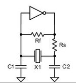
I am trying to learn about oscillators by studying some RF circuits, and I have a few questions about a Pierce oscillator. A simplified circuit consists of a XTAL, two capacitors that provide load capacity, a feedback resistor, a power limiting resistor and an inverting element (see attached pic). I learned that to achieve oscillations the inverter provides a 180° phase lag, and the XTAL with the two caps make a Pi-filter that provides another 180° of phase lag. Together we get 360° phase delay which is one of the requirements for stable oscillation (the other requirement being sufficient gain of the inverting element).
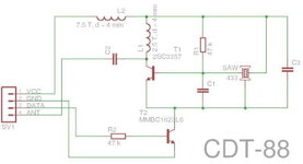
The RF circuit that I'm trying to understand is a 433.92 MHz ISM-band transmitter that is supposedly using a Pierce oscillator to transmit a carrier signal while the data is OOK-modulated. It uses a few resistors/caps, a NPN RF transistor with common emitter that acts as an inverting amplifier and a SAWR (surface acoustic wave resonator) instead of a crystal, (see attached pic).
My questions are:
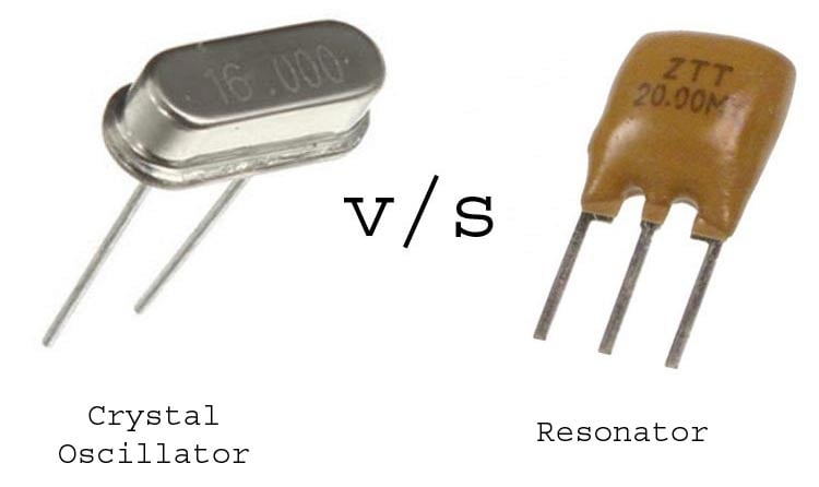
- How is a SAW resonator different from a crystal in this case?
- In many crystal datasheets manufacturers normally specify a maximum crystal load (drive level i.e. about a hundred uW). A higher drive power may permanently damage the crystal which is why the circuit has a power limiting resistor in place. Does a SAW resonator also need any power limiting resistors to avoid damage? The datasheets don't seem to specify any maximum drive level. The circuits don't normally have one. Is the bias resistor enough?
- Is a DC-blocking ceramic capacitor needed directly in series with the SAW resonator? I've seen some circuits that have it and others don't. What's the deal here?
Thanks in advance
I am trying to learn about oscillators by studying some RF circuits, and I have a few questions about a Pierce oscillator. A simplified circuit consists of a XTAL, two capacitors that provide load capacity, a feedback resistor, a power limiting resistor and an inverting element (see attached pic). I learned that to achieve oscillations the inverter provides a 180° phase lag, and the XTAL with the two caps make a Pi-filter that provides another 180° of phase lag. Together we get 360° phase delay which is one of the requirements for stable oscillation (the other requirement being sufficient gain of the inverting element).
The RF circuit that I'm trying to understand is a 433.92 MHz ISM-band transmitter that is supposedly using a Pierce oscillator to transmit a carrier signal while the data is OOK-modulated. It uses a few resistors/caps, a NPN RF transistor with common emitter that acts as an inverting amplifier and a SAWR (surface acoustic wave resonator) instead of a crystal, (see attached pic).
My questions are:
- How is a SAW resonator different from a crystal in this case?
- In many crystal datasheets manufacturers normally specify a maximum crystal load (drive level i.e. about a hundred uW). A higher drive power may permanently damage the crystal which is why the circuit has a power limiting resistor in place. Does a SAW resonator also need any power limiting resistors to avoid damage? The datasheets don't seem to specify any maximum drive level. The circuits don't normally have one. Is the bias resistor enough?
- Is a DC-blocking ceramic capacitor needed directly in series with the SAW resonator? I've seen some circuits that have it and others don't. What's the deal here?
Thanks in advance