andig
Junior Member level 3
Hi,
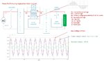
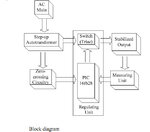
I still do not understand why you need a changeover. For AC-AC conversion you can do without batteries. Well your task becomes easier then. Probably you need not generate the sinewave!! Lets consider boost at the moment. If your input is 100volts and you need an output of 200volts then you need to add 100 volts. Thus you drive a buck-boost transformer to generate 100volts in-phase. You rectify the AC and what you get is a unipolar sinusoidal waveform. Feed this to a Bridge (just as in inverter). Drive the bridge with a PWM either in-phase (0-100% PWM produces 0-100Volts boost ) or out-of-phase (0-100% PWM produces 0-100Volts buck ). The attached block diagram (taken from http://www.suvik.com/static-stabilizer.php) should make things more clear.
Regards
Sougata
- - - Updated - - -
Hi,
I still do not understand why you need a changeover. For AC-AC conversion you can do without batteries. Well your task becomes easier then. Probably you need not generate the sinewave!! Lets consider boost at the moment. If your input is 100volts and you need an output of 200volts then you need to add 100 volts. Thus you drive a buck-boost transformer to generate 100volts in-phase. You rectify the AC and what you get is a unipolar sinusoidal waveform. Feed this to a Bridge (just as in inverter). Drive the bridge with a PWM either in-phase (0-100% PWM produces 0-100Volts boost ) or out-of-phase (0-100% PWM produces 0-100Volts buck ). The attached block diagram (taken from http://www.suvik.com/static-stabilizer.php) should make things more clear.
Regards
Sougata
- - - Updated - - -
Hi,
I still do not understand why you need a changeover. For AC-AC conversion you can do without batteries. Well your task becomes easier then. Probably you need not generate the sinewave!! Lets consider boost at the moment. If your input is 100volts and you need an output of 200volts then you need to add 100 volts. Thus you drive a buck-boost transformer to generate 100volts in-phase. You rectify the AC and what you get is a unipolar sinusoidal waveform. Feed this to a Bridge (just as in inverter). Drive the bridge with a PWM either in-phase (0-100% PWM produces 0-100Volts boost ) or out-of-phase (0-100% PWM produces 0-100Volts buck ). The attached block diagram (taken from http://www.suvik.com/static-stabilizer.php) should make things more clear.
Regards
Sougata