Continue to Site
Follow along with the video below to see how to install our site as a web app on your home screen.
Note: This feature may not be available in some browsers.
Power amplifierWhat's a PA?
Got it. So if the loadpull gets the impedance assuming Z, then in order to get the largest output power, I should ensure the 50ohm transfers to Z*. Am I right?No doubt that maximum power transfer is achieved if a PA of output impedance Z1 is terminated with conjugate impedance Z1*.
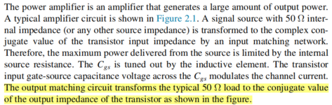
In usual RF termnology Zopt is understood as an external impedance. But in your drawing, Zopt is an impedance seen into the PA output, in other words its output impedance.
To avoid misunderstandings, you should correct the drawing annotation.
In usual terms, if you achieve maximum power transfer with load impedance Zopt, the output impedance of the PA is Zopt*.
Yeah, I know the difference between conjugation matching and power matching. I mean, after getting the optimum impedance, should I design the output matching network with the conjugation of the optimum inpedance or just optimum impedance? The picture below comes from "RF and mm-Wave Power Generation\[Z_{opt} \neq Z_{conj} \]
Optimum Loading Condition is particularly different for Power Amplifiers.Conjugate Matching is necessary and Sufficient Condition for Small Signal Amplifiers, this is true but the case diverges for Power Amplifiers.
You have to-absolutely-design a Matching Circuit so that while one Port having \[Z_{opt}\]
the Other Port will be simply 50 Ohm.Forget about \[Z_{conj}\] for Large Signal Amplifiers.
Definition : However there isn't Official Definition for Power Amplifiers, 0.25W Delivered Power and beyond can easily be accepted being as Power Amplifier.
But the author talks about Input Impedance Matching.As he said, Conjugate Matching is good enough for Input.Yeah, I know the difference between conjugation matching and power matching. I mean, after getting the optimum impedance, should I design the output matching network with the conjugation of the optimum inpedance or just optimum impedance? The picture below comes from "RF and mm-Wave Power Generation
in Silicon" written by Hua Wang.
The last sentence means the output matching, not input matching. Also, source pull is important.But the author talks about Input Impedance Matching.As he said, Conjugate Matching is good enough for Input.
But !
For an Optimum Performance ( Power or Efficency ) Input Impedance should also be examined in order to find Optimum Input Impedance ( Source Pull )
OK, Author's statement is wrong.Conjugate Matching is not considered in Power Amplifiers.The last sentence means the output matching, not input matching. Also, source pull is important.
Low Zout may cause the current increase and the PAE will decrease.for theoretical max power transfer, Zout = Zload, but for the most efficient operation of a power amplifier;
it should be designed with a low Zout ( resistive ) compared to the load - which could be 50 ohm ( resistive )
Therefore if the PA Zout is 0.5 ohm resistive, there is only a small loss in the PA and all the intended power ends up in the load.
I have seen both matching method in different books, really confused me.OK, Author's statement is wrong.Conjugate Matching is not considered in Power Amplifiers.
Wrong information..
this comment is non sequitur - can you offer background explanation ?Low Zout may cause the current increase and the PAE will decrease.
I'm not sure, just according to the loadline. Assuming the DC point dosen't change. If Zout<Zopt, the swing of current could achieve Imax while the voltage COULDN'T achieve the Vmax. In the same time, the output power doesn't equal to (Vmax*Imax)/8, which should be (Vmax*Imax*Zout/Zopt)/8, then the PAE also decrease.this comment is non sequitur - can you offer background explanation ?
The optimum output impedance.you haven't defined Zopt
To get maximum output power not the best PAE.you haven't defined Zopt
Yeah, always should trade off between these three contours.Dear Junhao..
When you design a Power Amplifier, you can find 3 \[Z_{opt}\] for;
-Max Power Gain
OR
-Max. Efficiency
OR
-Max. Delivered Power
So you do your choice and the compromise between these 3 point ( and of course their contours ) will give you an insight about what'll happen.
For linear amplifiers (class A/AB/B/C) this makes no sense. Dissipation in the PA is determined primarily by bias conditions, not output impedance.for theoretical max power transfer, Zout = Zload, but for the most efficient operation of a power amplifier;
it should be designed with a low Zout ( resistive ) compared to the load - which could be 50 ohm ( resistive )
Therefore if the PA Zout is 0.5 ohm resistive, there is only a small loss in the PA and all the intended power ends up in the load.
When you design a Power Amplifier, you can find 3
Zopt
Z_{opt} for;
-Max Power Gain
OR
-Max. Efficiency
OR
-Max. Delivered Power