bhathi123
Newbie level 5
Consider these equations for diode rectifier;
I(V) = Is(e^(alpha*V) -1) -----------(1)
Let diode voltage be V=Vo+v --------------(2)
Then, Using taylor series for the diode current I(V) [equation (1)] we have;
 ; where Io=I(Vo)
 ; where Gd is the dynamic conductance (Gd=1/Rj, where Rj is the juction resistance at Vo)
Then for diode rectifier we have;
 ----------(3)
then diode current;

Therefore we can say is the rectified current. Using a low pass filter we can simply get rid of the higher
frequency components
[Microwave Engineering 2nd Ed, David M. Pozar, paged 560-563]
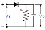
What I cannot understand is these equations are derived from the simple assumption that Input Voltage [equation (3)] is across the diode. But in a
rectifier circuit like this [figure below] will not have Vin across the diode. Then how can I use these equations in this situation?

I(V) = Is(e^(alpha*V) -1) -----------(1)
Let diode voltage be V=Vo+v --------------(2)
Then, Using taylor series for the diode current I(V) [equation (1)] we have;
Then for diode rectifier we have;
then diode current;
Therefore we can say
frequency components
[Microwave Engineering 2nd Ed, David M. Pozar, paged 560-563]
What I cannot understand is these equations are derived from the simple assumption that Input Voltage [equation (3)] is across the diode. But in a
rectifier circuit like this [figure below] will not have Vin across the diode. Then how can I use these equations in this situation?
