engr_joni_ee
Advanced Member level 3
Hi,
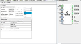
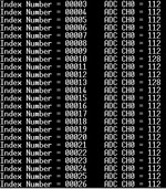
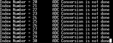
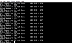
I am using PIC18F25K80 and here is my code. I don't get the correct values from ADC. I am using MPLAB MCC.
I am using PIC18F25K80 and here is my code. I don't get the correct values from ADC. I am using MPLAB MCC.
Code:
void main(void)
{
// Initialize the device
SYSTEM_Initialize();
__delay_ms (500);
// Add your application code
ADC_Initialize();
int ADC_Result = 0;
while(1)
{
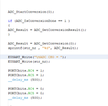
ADC_StartConversion(0);
__delay_ms (500);
ADC_Result = ADC_GetConversion(0);
sprintf(str_nr , "%d", ADC_Result);
EUSART_Write("\tADC CH0 = ");
EUSART_Write(str_nr);
__delay_ms (500);
}
}