Continue to Site

Welcome to EDAboard.com

Welcome to our site! EDAboard.com is an international Electronics Discussion Forum focused on EDA software, circuits, schematics, books, theory, papers, asic, pld, 8051, DSP, Network, RF, Analog Design, PCB, Service Manuals... and a whole lot more! To participate you need to register. Registration is free. Click here to register now.

[Moved] Precision rectifier shows lower values than what i have input

Status
Not open for further replies.

GeekDOn

Newbie level 3
Joined
Apr 28, 2014
Messages
3
Helped
0
Reputation
0
Reaction score
0
Trophy points
1
Activity points
29
Hi All

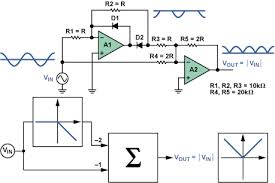
i have a problem with my full wave precision rectifier using LM358 , i observe lower voltages than what i have as input,
firstly i drew the circuit on a simulator and fed in dc as input with a variable resistor connected, the output measured is the same as the DC input ,

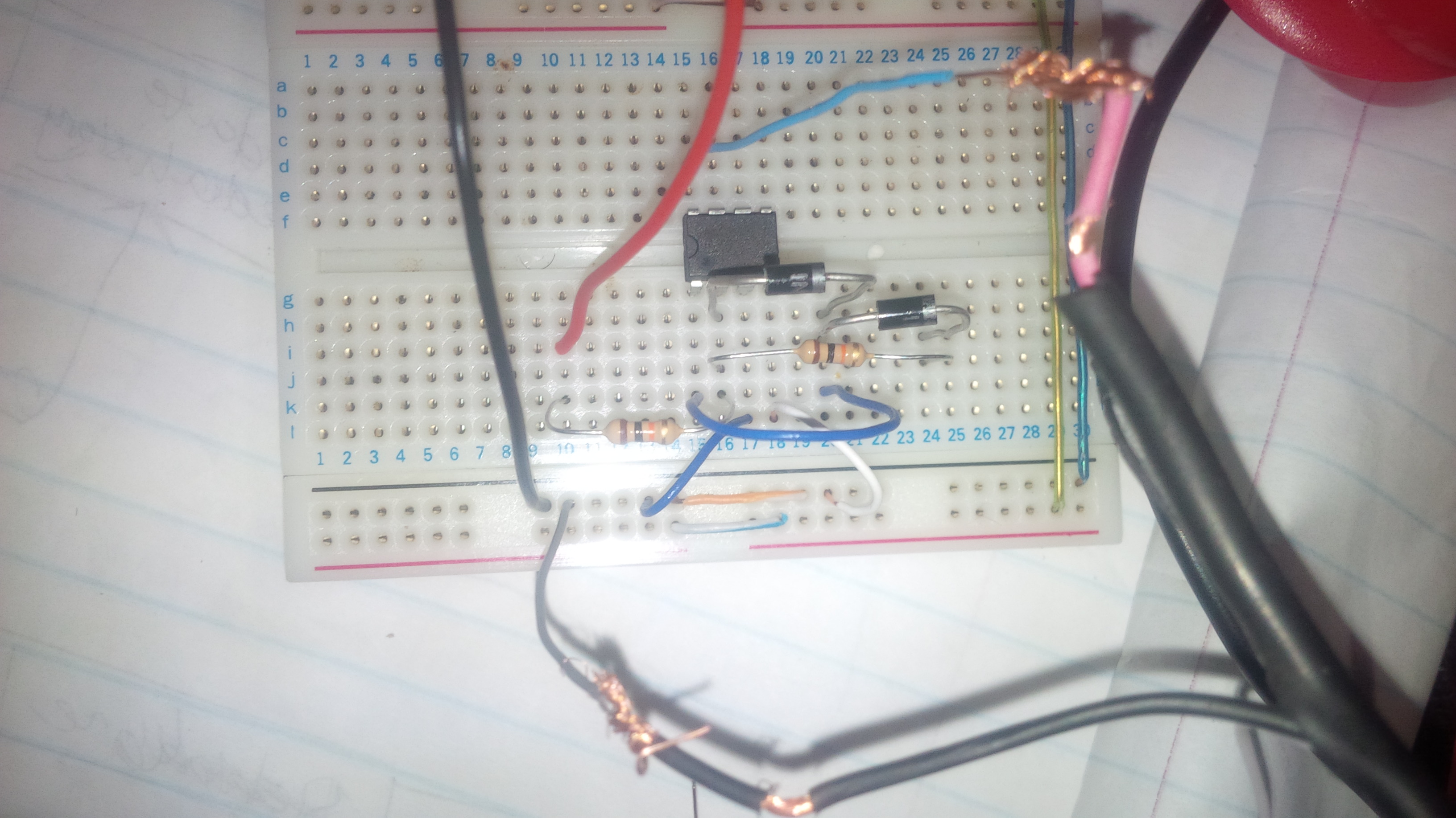
when i built the hardware i put an 8V battery as input , but on the output of the LM358 my multimeter reads voltages of around 3,5 Volts, i resorted to building a more simpler half wave rectifier which does the same, the question is , where did i drop that much volts?

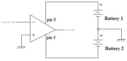
When i put power on pin 8 of the LM358, with nothing on the Input (inverting input) i get some voltage of ~89mV , i cannot be generating power from nothing , where is the voltage coming from? since i do not have any input ?

:sad:
 

Re: Precision rectifier shows lower values than what i have input

Please post your circuit.
 

Re: Precision rectifier shows lower values than what i have input

not sure if you want the circuit diagram of the precision rectifier or the one i have built .. but i have attached the physical circuit , you can find the diagram here : https://en.wikipedia.org/wiki/Precision_rectifier
i used LM358 as explained before, if you can try to use my scenario and tell me your observation?


Your circuit is an inverting half wave precision rectifier. This means that a positive voltage at the input will be transalted to zero at the output, while a negative voltage will be translated in a positive voltage, with the same absolute amplitude (you set the gain to unity) at the output.
But to do this the op-amp needs a dual supply voltage (pin 8 - GND of the circuit and GND of the circuit - pin 4), while I see you used a single supply source.
 

Hi

Thanks for the Reply, im not really clear on it , from the diagram below , Pin 8 is my Vcc , while Pin 4 is my ground ,
when you say dual supply , do you mean i should modify my circuit as the one below:
5430428300_1398757724.jpg


Secondly :
from what you have explained its clear that
If Vin< 0, Vout = -Vin , and when
Vin > 0 , Vout = 0 the problem here is that i measure some ~82mV

but the Logic makes sense, if you can just confirm for me if the attached rectifier should work?
 

Yes, I think your circuit can work. As I said, you need a dual supply like this:


There are a number of full-wave precision rectifiers that only require a single power supply, see this.

Edit: This one seems fairly simple requiring only two op amps or one dual (single-supply types), three resistors and a diode.

Below is a simulation of the circuit.

Precision Rectifier.gif
 
Last edited:

Status
Not open for further replies.

Similar threads

Part and Inventory Search

Welcome to EDABoard.com

Sponsor

Back
Top