Continue to Site

Welcome to EDAboard.com

Welcome to our site! EDAboard.com is an international Electronics Discussion Forum focused on EDA software, circuits, schematics, books, theory, papers, asic, pld, 8051, DSP, Network, RF, Analog Design, PCB, Service Manuals... and a whole lot more! To participate you need to register. Registration is free. Click here to register now.

How to calculate AC input power for RF-DC rectifier by cadence

Asmaa Sayed

Newbie
Joined
Jan 19, 2024
Messages
1
Helped
0
Reputation
0
Reaction score
0
Trophy points
1
Activity points
17
Hi everyone,
I’m currently studying active rectifiers, and I’m trying to calculate the AC input power for an RF-DC rectifier. I’m using the following formula:

PAC=1/T *integral(Vin(t) *Iin(t))
here is the cadence equation
1706821619043.png

Can anyone help me with the calculations? I’d really appreciate it!
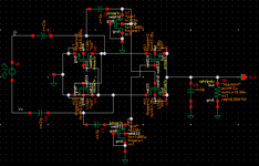
Here is the circuit schematic:
Thanks in advance.BootstrappingPMOS.png
 
The general approach is to examine which components conduct during one half of the cycle. Determine each component's impedance, or current-carrying performance, or voltage-dropping ability. Use standard formulas to extract information that's missing.

Since you have AC going through capacitors, they present an impedance which might vary during each cycle. Anyway tally up all branches of your circuit (series and parallel). This gives you an idea how much power your circuit can admit.

Regarding power admitted during the other half of the cycle, you can assume it's identical as long as your circuit is symmetrical in the way .

Your bootstrap circuit resembles a Cockcroft-Walton voltage doubler. You can expect current surges at startup. This is because uncharged capacitors begin by appearing as very low ohms. It will take many cycle before current levels reach stable running operation.
 

LaTeX Commands Quick-Menu:

Similar threads

Part and Inventory Search

Welcome to EDABoard.com

Sponsor

Back
Top