Continue to Site

Welcome to EDAboard.com

Welcome to our site! EDAboard.com is an international Electronics Discussion Forum focused on EDA software, circuits, schematics, books, theory, papers, asic, pld, 8051, DSP, Network, RF, Analog Design, PCB, Service Manuals... and a whole lot more! To participate you need to register. Registration is free. Click here to register now.

how to calculate AC power by cadence?

jerald woo

Newbie
Joined
Aug 8, 2023
Messages
2
Helped
0
Reputation
0
Reaction score
0
Trophy points
1
Activity points
35
Hi, I'm studying about a passive rectifier.
I designed the conventional rectifier circuit by Cadence tool.
When I calculated the PCE (Power Conversion Efficiency), I only get around 60%.
(I tried to find the optimized point, So these circuit parameters are pretty optimized.)

But many papers say this conventional rectifier has almost 80% PCE at optimized point.
So I think that the input power calculating might be wrong.
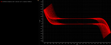
Unfortunately, I didn't consider the power factor between input voltage and input current.
(I didn't consider 'cosθ' in the equation of the first figure)

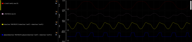
Now I notice what is the missing point of my calculation, but I don't know how to calculate it by Cadence.
Cadence calculator don't have functions for AC power or power factor calculation. (second figure)

Let me know how to calculate AC power by Cadence.
Or if there are other missing points, please tell me about it.

Thank you for reading my question.

passive rectifier.png
cadence calculator.png
 
I've seen discussions here about using Cadence software though I haven't used it myself.

1.
Your list has an item called WaveVsWave. Could that item let you compare a voltage waveform with Ampere waveforms?

Or else you might need to eyeball an Ampere waveform and see whether it's misaligned with the voltage waveform.

2.
Power is Watts. Watts is calculated as Volts x Amps. There are wattmeters which contain circuitry for performing multiplication. I suspect building a wattmeter project involves an op amp or two
to perform multiplication

Does your simulator contain any component called a wattmeter, or power meter, or efficiency meter?
 
Thank you for your answer.

First I used the 'waveVSwave' function to compare the voltage and ampere waveform.
The result is in first figure.
I thought that this function is not useful for me.

Second I multiplied voltage and ampere waveforms.
Before multiplying, I found that the voltage waveform are not same format with the ampere waveform (like sine wave).
So I thought that the power factor might be complicated.
And after I multiplied these two waveforms, I noticed that I can't get any phase information.
Also I used phase function of Cadence, I can get some strange waveform in second figure.

Third I tried to find any component for measuring power.
But I don't have any component for measuring power.

As a result, still, I don't know how to calculate the AC power by Cadence.
 

Attachments

  • waveVSwave.png
    waveVSwave.png
    103.6 KB · Views: 72
  • voltage and ampere waveform.png
    voltage and ampere waveform.png
    51.9 KB · Views: 71
Concepts underlying power factor error & PF correction are not readily obvious.

I had to re-read articles until I realized the elevated power level misleads us into thinking the supply is really working harder. The Ampere level is elevated, and registers on instruments, yet evidently it all arises from inductive behavior.

Simulations can be correct in showing the action and calculating values mathematically, nevetheless we must examine in order to grasp what's going on.

My simulation compares situations before and after PF correction. in both cases the load receives the same power. Whereas in circuit A: power through the supply is exaggerated causing power factor error, yet in B power is reduced when the capacitor is installed.

If you examine your own calculations, you may discover a similar elevating effect, in your circuit capacitive rather than inductive.

power factor error simulations ( before and after correction).png
 
Thank you for your answer.

First I used the 'waveVSwave' function to compare the voltage and ampere waveform.
The result is in first figure.
I thought that this function is not useful for me.

Second I multiplied voltage and ampere waveforms.
Before multiplying, I found that the voltage waveform are not same format with the ampere waveform (like sine wave).
So I thought that the power factor might be complicated.
And after I multiplied these two waveforms, I noticed that I can't get any phase information.
Also I used phase function of Cadence, I can get some strange waveform in second figure.

Third I tried to find any component for measuring power.
But I don't have any component for measuring power.

As a result, still, I don't know how to calculate the AC power by Cadence.
Hi Jerald,
I am having the same problem. I don't know how to calculate power factor when voltage and current waveforms are not sinusoidal. This is causing problems in calculating the real power which is required to calculate the power efficiency. Were you able to figure out how to do this?
Thanks,
Anand
If the waveforms arn't Sinusoidal then Power Factor is only 50% of the problem, you are then in the realms of 'Total Harmonic Distortion' which to measure usually requires a FFT of the waveform. A truely Sinusoid current has low THD AND is in phase with the votage. In the time domain simulator you should be able to multiply instantanious V * Instantanaeous Amps to give a resulting instantanous power then use a RMS function to get the resulting RMS power.
 
Last edited:
Hi,
I am having the same problem. I don't know how to calculate power factor when voltage and current waveforms are not sinusoidal
Over a dedicated time (fundamental period time, or integer multiples of it) calculate:
* V_RMS
* I_RMS
* apparentPower by: V_RMS × I_RMS
* truePower by: 1/t ×( integral of (V(t) × I(t)) )
* power factor by: truePower / apparentPower

Klaus
 
One description of RMS power states it can be
gauged (for any waveform) by heating a resistor
to a given temperature, then (experimentally)
discovering the DC voltage whose heating effect
is identical.

There is a coefficient (1.1 if recall) relating one
to the other.

I imagine an incandescent bulb's brightness does the same thing.
 
What are R0 and R1? Are they components of your rectifier circuit (if so, why?) or modeling source (e.g. antenna) impedance? In the latter case, you are calculating Vin incorrectly.

Correction, I see you are measuring Vin after R0/R1, so everything correct.
 
You have to find Average Power using this equation. You cannot find this power by multiplying voltage and current.
\[ P_{in}=0.5*Re(V_{in(AC)}*Conj(I_{in(AC)})) \]
 

LaTeX Commands Quick-Menu:

Similar threads

Part and Inventory Search

Welcome to EDABoard.com

Sponsor

Back
Top