Continue to Site

Welcome to EDAboard.com

Welcome to our site! EDAboard.com is an international Electronics Discussion Forum focused on EDA software, circuits, schematics, books, theory, papers, asic, pld, 8051, DSP, Network, RF, Analog Design, PCB, Service Manuals... and a whole lot more! To participate you need to register. Registration is free. Click here to register now.

Measuring leakage inductance for multiple winding transformer

Learner1234

Newbie level 6
Joined
Jan 20, 2024
Messages
12
Helped
0
Reputation
0
Reaction score
0
Trophy points
1
Location
Australia
Activity points
98
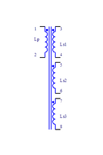
Hi guys. I have a ferrite transformer consisting of one primary winding and 3 secondary windings. Now I want to measure the leakage inductance at the primary side, so I need to short the secondary windings. Most of the literature I have read, there is only one secondary winding so it's pretty straightforward how to short the secondary side. But now, I have 3 windings at the secondary side, I am considering of 3 possible ways to measure the leakage inductance at the 'primary side',

1. Short 3 and 4, 5 and 6, 7 and 8
2. Short each winding one by one while leaving other windings open, e.g. 3 and 4 shorted, 5 and 6 open, 7 and 8 open, etc.
3. Short 4 and 5, 6 and 7, 8 and 3.

Assume that my short circuit is perfect, what will be the result for above 3 ways of measuring leakage at primary side?

Now suppose that I have gapped the ferrite core. What will happen to leakage inductance at primary side for above 3 situations?
 

Attachments

  • How to measure leakage inductance.png
    How to measure leakage inductance.png
    2.7 KB · Views: 60
You would short all three outputs to measure the input leakage inductance.
They can all be shorted to the same point or shorted separately, but all be shorted at the same time.

If they are not all shorted than you may see a somewhat higher primary leakage inductance.

Not sure how the gap will affect the leakage inductance, but I would expect to be less.
I have shorted all secondary windings at a single point. When measured from primary it was around 45uH with a gap of 0.57mm. However when I removed the gap and then measured, it was around only 15uH. So which one is true leakage inductance?
 
Generally transformer main- and leakage inductance forms a N×N matrix. What you consider as primary inductance depends on transformer application. Shorting all secondaries fits many applications but not all.

Effect of gap depends on winding geometry and gap position.
 
Hi. Actually I have to use this transformer for AC to DC LLC resonant converter with multiple outputs. The leakage inductance plays an important role in determining resonant tank values. Primary inductance should be around 200uH and in such a case it was possible only if I gap the core. That's done. Now I have to measure leakage inductance so that if it's smaller than desired then I introduce external resonant inductor. The required total resonant inductance is 37uH. So my question still same that do I consider transformer leakage inductance with or without gap in this scenario. My guess is to consider the leakage inductance with gap as I have to use transformer in gap format. However in such case transformer leakage inductance is already above 37uH, as 45uH.
 
At what frequency do you measure leakage inductance?
You cannot realistically do an LLC with three outputs and one transformer.
Its just not possible to get the leakage inductance for each coil to be exactly what you want.

Or Is it one main output, and two <100mW outputs?

Even an extra low power bias coil output is dodgy with an LLC.

I am sorry to tell, but there is only one way to realistically assess what leakage inductance you have.
And that is to make a quick PCB with the transformer in it, and add the resonant capacitor in series with the primary.
Then put in a square wave at your desired upper resonant frequency, and see if you get a nice sine wave or not.
Or better still, sweep the frequency , and see at which frequency you get max amplitude, and that is the resonant frequency
Add some resistance in series so that you dont draw too much current whilst doing this.

By the sounds of it, You are trying to do it with a quick measurement with an LCR meter, and that cannot properly be done.

Or if you want, the attached (LTspcie and PNG) shows you how to make a leakage inductance measurement. with a 555
--- Updated ---

Also, i attach a folder showing multiple ways of measuring the leakage inductance.
 

Attachments

  • 555 inductor measurement.zip
    1.3 KB · Views: 54
  • Inductor measure 555.png
    Inductor measure 555.png
    44.4 KB · Views: 48
  • inductor measure.zip
    2.7 MB · Views: 60
Last edited:
Thank you @cupoftea for the documents.
What you offered is some other way to measure leakage inductance. However, my question still same that do I need to measure leakage inductance with gap as that will be used in actual transformer or without gap which will not be the case for actual transformer used.
 
For LLC, you need to measure the leakage as it will be used...so as you say, with the gap.
Split bobbins or section winds are popular for LLC...but yes, you can trim your leakage inductance with a gapping exercise.

I give here other document, is relevant for you. By the way, it is courtesy of FvM, who kindly supplied it some time back.


Attachments

  • Leakage inductance and core gapping.zip
    692.9 KB · Views: 62
Last edited:
Hi @cupoftea thanks for the attachment file by FvM. I still wonder then why my LCR meter is measuring leakage as 45uH with gap and only 15uH without gap when measured from primary side. I have distributed around 0.57mm gap equally to EE core three sections (center and two outer) The magnetizing inductance of primary winding is 2.15mH without gap and with gap its around 270uH. Where I'm wrong about it. I'm using standard LCR meter of model UYIGAO UA4070L to measure the leakage inductance. I have shorted all secondaries at one single point in both cases, with or without gap.
 
I still wonder then why my LCR meter is measuring leakage as 45uH with gap and only 15uH without gap when measured from primary side.
I agree that the values sound surprizing. Either it's an effect of a special winding geometry or the LCR meter has problems. Can you show a sketch of the winding geometry?
 
I agree that the values sound surprizing. Either it's an effect of a special winding geometry or the LCR meter has problems. Can you show a sketch of the winding geometry?
I'm using,
2 secondaries in full wave center-tapped configuration (one for main power and other for minor power) and
2 secondaries in half wave configuration (one as primary auxiliary winding and 2nd for some other purpose).

I have used primary winding in interleaved configuration with main full wave center-tapped secondary winding in between the sandwich of primary winding. The other, 2nd minor full wave center-tapped winding and 2 half wave secondaries are wound on top of it.

I have also noticed that if I introduce flux band outside the ferrite core using a copper strip then leakage inductance of gapped core decrease from 45uH to 35uH.
 
I cant find a manual for your LCR meter, but the brief i found on it says L is from 20mH to 2H, so i woudlnt expect it to do low uH measurements well.

Use the resonance method above to give you a true value for your leakage inductance.
LCR meters are very often screwed because somebody puts a capacitor on it with a high voltage....and they never seem to work well after that...even on the inductance range.

The whole thing with LCR meters needs sorting out.
If other people use it, then garanteed someone has screwed it with a high voltage cap on it.
So basically, any LCR meter needs to come with a calibration kit so that you can put it through its paces before taking any measurement, -to see if its
likely to be OK or not.

But as i said, use the home brew resonance method that i give above. Do it that way instead.

...and the meter you point out looks like a trashy thing (from what i saw from other peoples posts about it on web) for measuring only high value inductors.
 
Last edited:
@FvM Plz find attached here the sketch of geometry.

@cupoftea I guarantee that LCR meter is not tempered.

As written in the following link from encyclopedia magnetica, under transformers heading that air gap increases the leakage inductance so contrary to what FvM said, or may be they did not want to say anything about effect of winding geometry.
air gap vs leakage inductance
Note that in sketch pin 2 not used
 

Attachments

  • Leakage inductance vs air gap vs geometry.jpg
    Leakage inductance vs air gap vs geometry.jpg
    293.7 KB · Views: 47
Last edited:
..i dont think anybody disagrees that leakage inductance increases with air gap...it does...but its a question of how much...when you introduce a gap, you get fringing fields, and these naturally do not allow as good coupling, in other words, your leakage increases.

If you have sectioned coils, then your leakage will likely increase more as you increase air gap....as opposed to the usual nice coils which evenly go over the whole length of the bobbin.

I bet with an "Integrated gap" core, you would not get so much increase of leakage inductance with air gap....because the fringing field is less.

There is an app note on the web showing how one can tune one's leakage inductance in an LLC transformer by adjusting the air gap...i think its by fairchild or onsemi?

Can you just do a simple diagram, that will show whether you have whole layers or not?.....or do you have one coil on the RHS, and the other coil on the LHS, like in a sectioned bobbin?

If the air gap gets ridiculously big, then leakage inductance will get ridiculously large........well, as large as the air-cored equivalent can make it.
But remember, air gaps in all (even LLC) transformers are usually quite small...because you dont want those fringing fields causing hysteresis heating in your coils.

What is your upper resonant frequency in the LLC?......short the secs, then hit the primary with a square wave of that frequency, then tune the capacitance till you get max amplitude.....then you are on resonance.......then you can calc the leakage inductance, and you are doing so at exactly your intended switching frequency, so it cannot possibly be a wrong value....that is the best measurement of leakage inductance that you will get.

Your LCR will tell lies unless you go back to its manufacturer to ask every detail

Page 10 (AKA page 12) of this shows leakage inductance vs gap length for an llc transformer with the shown winding geometry.
 
Last edited:
Can you just do a simple diagram, that will show whether you have whole layers or not?.....or do you have one coil on the RHS, and the other coil on the LHS, like in a sectioned bobbin?

What is your upper resonant frequency in the LLC?......short the secs, then hit the primary with a square wave of that frequency, then tune the capacitance till you get max amplitude.....then you are on resonance.......then you can calc the leakage inductance, and you are doing so at exactly your intended switching frequency, so it cannot possibly be a wrong value....that is the best measurement of leakage inductance that you will get.

Page 10 (AKA page 12) of this shows leakage inductance vs gap length for an llc transformer with the shown winding geometry.
@cupoftea & @FvM plz attached here find the transformer winding geometry that I used.

Will try to do the experiment that you just mentioned to find leakage inductance by the method of injecting square wave to then calculate whether it's 45uH or else...interesting. I assume that amplitude of signal does not matter much and can be around 5V to 12V.

Table 2 of AN-4151 shows that leakage inductance 'decreases' with increasing the gap length...strange isn't it? Also step-7 reads that gap length does not affect leakage inductance value much and it's the number of turns (for sectional bobbin) and winding configuration that affects the leakage inductance.
 

Attachments

  • Transformer winding geometry.jpg
    Transformer winding geometry.jpg
    476.7 KB · Views: 37
You could just make a footprint for "an inductor" and do a prototype layout and see for yourself. Then
just change or adjust the "resonant inductor" to suit.

Just put dummy laods on the secondaries at first.
Then switch the circuit at a high frequency, then reduce fsw until you get to the resonant frequency......the resonant frequency is where your vout = vin x ns/np
 
..i dont think anybody disagrees that leakage inductance increases with air gap...it does..
Typically Ls decreases with increased air gap, also in the linked Onsemi LLC application note. With unusual winding geometry, the relation can be different. The reported 45 uH versus 15 uH relation doesn't sound reasonable and might indicate a measurement artifact.
 
Last edited:
regarding the post #16 above and continuing
.......Obviously dont go too low in frequency as you will go "over the hill" into the capacitive region.
I think in your case, it is necessary to do this...as you will doubtless get different coupling to each coil....so just do the open loop experiment as described and see how it turns out.
May i ask the power level and application?....i ask because they way you have it, will not work out for high power levels in certain applications.

And Sorry yes, i got it the wrong way round with leakage and gap size.
 

LaTeX Commands Quick-Menu:

Part and Inventory Search

Welcome to EDABoard.com

Sponsor

Back
Top