Continue to Site

Welcome to EDAboard.com

Welcome to our site! EDAboard.com is an international Electronics Discussion Forum focused on EDA software, circuits, schematics, books, theory, papers, asic, pld, 8051, DSP, Network, RF, Analog Design, PCB, Service Manuals... and a whole lot more! To participate you need to register. Registration is free. Click here to register now.

What is the relationship between leakage inductance and core gap size?

Status
Not open for further replies.
T

treez

Guest
Hello,
Supposing I have an ETD39, N87, Epcos Ferrite transformer.
Ns = 30
Np = 30

I put the ungapped ETD39 core halves into the bobbin and measure the leakage inductance.
Now I do the same again, but this time with a 0.2mm centre leg gapped ETD39 core.

…Which of the above two leakage inductance measurements is greatest?

ETD39 Ferrite core datasheet
https://www.farnell.com/datasheets/1859555.pdf
 

I put the ungapped ETD39 core halves into the bobbin and measure the leakage inductance.
Now I do the same again, but this time with a 0.2mm centre leg gapped ETD39 core.
You say you measured it. What's the result?

I believe we discussed the topic before.

Leakage inductance of a regular transformer (including interleaved winding design) is (in a first order) an air core inductance. It's only weakly influenced by core permeability and air gaps.
 

You say you measured it. What's the result?
Sorry I haven't yet got clearance to buy these cores...I havent actually measured it, I was just kind of putting the question in an abbreviated way.
 

I put the ungapped ETD39 core halves into the bobbin and measure the leakage inductance.
Now I do the same again, but this time with a 0.2mm centre leg gapped ETD39 core.

The magmatic reluctance will be increased due to the gap. This will affect the self inductance of the primary coil.
The leakage inductance will mostly depend on the geometry of the winding. In the first order, it will not depend on the core.
Leakage is with respect to the mutual inductance and the mutual inductance will depend on the physical closeness of the primary and secondary windings.
You can put 30 turns using a very fine wire. The leakage inductance will be very small.
 

People often say that increasing the gap length increases leakage, but this is only true under the assumption that as the gap is changed, the turns are also changed to maintain constant magnetizing inductance. Merely changing the core material or gap length, while keeping Np and Ns fixed, doesn't significantly affect leakage, to a first order.
 

Thanks,
The thing is that the equation at the bottom of page 954 of the following (attached) document…

“Design guideline for magnetic integration in LLC resonant converters”

..shows that the leakage inductance increases with the square of the number of primary turns. Again, do you believe that this is true for NON-section wound transformers aswell?
 

Attachments

  • Design guideline for magnetic integration in LLC resonant converters.pdf
    430.5 KB · Views: 193

shows that the leakage inductance increases with the square of the number of primary turns. Again, do you believe that this is true for NON-section wound transformers aswell?
New topic?
Obviously it is, if winding geometry doesn't change otherwise.
 
  • Like
Reactions: treez

    T

    Points: 2
    Helpful Answer Positive Rating
Obviously it is, if winding geometry doesn't change otherwise.
What surprises me is that the leakage increases as with the square of the turns.
 

If you assume that the coupling factor is independent of number of turns, leakage is a constant fraction of the main inductance which also is also a function of n².
 

Doesn't matter, leakage and magnetizing inductance will both scale the same way, so long as the winding geometry is constant. Otherwise you'd have k changing with the number of turns, which wouldn't make sense.
 

This is all particularly interesting, and some recent experimentation here with a gapped interleaved 1:1 ratio winding suggests that where the gap is located can have a very significant effect on the coupling and leakage inductance.

I first tried this with large gapped EE cores and the results were far from satisfactory.
A similar winding technique (interleaved 1:1 foils) produced a vastly better result when wound on the U part of a UI core set with the gap external and well away from the winding.

I am not exactly sure why, but I have deep suspicions about fringing around the gap, and eddy currents being larger in the inner foil closest to the gap in the very first inner turn.

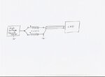
A sensitive test for this, is the following circuit:
Gap.jpeg

Drive the circuit with high amplitude square waves, like 30v peak to peak at 100 Khz. If the 1:1 transformer is "perfect" there should be nothing to see on the output. Any leakage inductance or imbalance will produce square waves and ringing on the output.
Several volts out of it for a crappy transformer.
Only a couple of millivolts out without any ringing on something really nice.

And amazingly it works just as well with or without the I placed across the U core, or with any gap size.
 
Drive the circuit with high amplitude square waves, like 30v peak to peak at 100 Khz. If the 1:1 transformer is "perfect" there should be nothing to see on the output. Any leakage inductance or imbalance

Square wave at 100kHz contains lots and lots of harmonics and that makes interpretation of the results difficult. If you do the same experiment with sine wave, the results will be much more cleaner. Ringing is always due to bandwidth limitations. See, for example, https://en.wikipedia.org/wiki/Gibbs_phenomenon and cannot be correlated with leakage inductance.
 

Square wave at 100kHz contains lots and lots of harmonics and that makes interpretation of the results difficult. If you do the same experiment with sine wave, the results will be much more cleaner. Ringing is always due to bandwidth limitations. See, for example, https://en.wikipedia.org/wiki/Gibbs_phenomenon and cannot be correlated with leakage inductance.

Yes indeed, and the ringing I was seeing was at around 1.9 Mhz, with 100 Khz drive.

Interpretation is dead easy.
If there is any output at all from that test circuit, something is not working at all well.

Square wave drive is what most switching power supplies get to work with, and the very nasty spikes and ringing produced are the problem we are attempting to solve.

Testing a flyback choke with sine waves makes no sense at all.

Ringing in an LC circuit is caused by resonance.
 

Yes indeed, and the ringing I was seeing was at around 1.9 Mhz, with 100 Khz drive.

I shall interpret that your core has failed around 1-2 MHz. It is absorbing too much of energy around this frequency.

It is impossible to physically overlap the two winding perfectly and leakage will be a fact of life. How much is acceptable is dependent on the geometry and personal considerations (how much leakage you are ready to accept). Also the leakage inductance can be defined independently for the two coils but it will still depend on the coupling between the two. In that sense the definition itself is not robust.

The choke is acting as a low pass filter and the ringing is due to the high frequency cut off.
 

The original problem had nothing to do with the winding method.
Its pretty difficult to do much better than with two interleaved foils.

As soon as the air gap was removed from the centre limb of the winding the problems entirely disappeared.

You can argue, but that is the effect I observed, and the improvement was dramatic.

I have often wondered about the wisdom of gapping the centre limb of a transformer, and then winding right over the top of the gap.
Its an easy enough experiment for anyone here to try for themselves.

If you do not have a UI core handy, try it with just half an E core with a lump of ferrite across the top (the other E core half turned around maybe).

I think you may be amazed at how much the coupling is improved with far less of the associated problems usually blamed on excessive leakage inductance.
 

I have often wondered about the wisdom of gapping the centre limb of a transformer, and then winding right over the top of the gap.
Its an easy enough experiment for anyone here to try for themselves.

I completely agree with your observation on the fringe effect. I am only trying to point out the theoretical aspects.

Once the manufacturers have decided on a style, it is very difficult for them to change.

I think it is better to equally distribute the total gap over the three legs. I may be wrong (as usual) but of course you can certainly find one manufacturer who will strongly advise against it.
 

Its not a very widely discussed topic.
The general assumption is usually either fit an equal gap, or buy factory gapped parts with a short centre leg. That may be fine and work well most of the time.

But if you are pushing the flux swing limits with a DCM flyback type topology, and it needs a very large gap, it may be of vital significance where that gap is located.

I suppose that raises the issue of radiated H field and EMI.
I really no not know, but I doubt if an external gap would be an improvement for that aspect.
But the copper band around the outside may offer a solution to that problem without compromising fringing in the main winding.

I may play around with this some more. I would be very interested to hear the results, experiences, and ideas of others regarding all this.

But getting back to the title of the thread topic:
What is the relationship between leakage inductance and core gap size?
I doubt if gap size really has any effect on leakage inductance unless the winding surrounds the gap. If it does, you may be in trouble.

And what might look like leakage inductance, and test as a measurable leakage inductance, may mostly be due to the effects gap fringing.
 

A simulation to illustrate my previous comment:
Leakage inductance of a regular transformer (including interleaved winding design) is (in a first order) an air core inductance. It's only weakly influenced by core permeability and air gaps.

We have a simple non-interleaved transformer, axisymmetric core (e.g. P core) for ease of simulation, the results can be roughly applied to E shaped cores. The inductance of the inner winding is measured with outer winding open (Lh) and shorted (Ls).

Three cases, ungapped core, gapped core and core with "distributed" gap, e.g. powder or low µr ferrite. Effective µr of second and third case is similar.

ungapped2000.png

gapped.png

ungapped50.png

The simulation supports the claim that leakage inductance is only weakly influenced by core permeability and air gaps, but there is some influence. This can be seen by comparing with Lh and Ls of an actual air core transformer.

air.png

Although a considerable part of the leakage inductor field goes through air, there's still 2/3 conducted by core material and the total reluctance respectively about 1/3 compared to pure air core.
 
Status
Not open for further replies.

Part and Inventory Search

Welcome to EDABoard.com

Sponsor

Back
Top