Continue to Site

Welcome to EDAboard.com

Welcome to our site! EDAboard.com is an international Electronics Discussion Forum focused on EDA software, circuits, schematics, books, theory, papers, asic, pld, 8051, DSP, Network, RF, Analog Design, PCB, Service Manuals... and a whole lot more! To participate you need to register. Registration is free. Click here to register now.

Pushpull SMPS has leakage inductance problems?

cupoftea

Advanced Member level 5
Joined
Jun 13, 2021
Messages
2,611
Helped
54
Reputation
108
Reaction score
115
Trophy points
63
Activity points
13,685
Hi,
Do you agree, the Pushpull SMPS must generally be used with an active snubber to regenerate primary side leakage inductance energy?

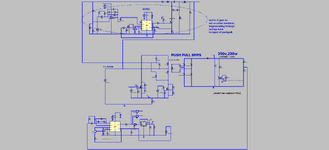
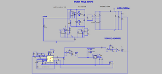
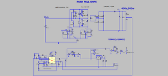
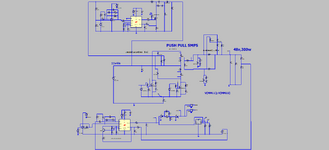
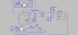
The attached (LTspice and PNG schems) shows a 200W pushpull with vin = 11.4V, and Vout = 350V, and an active snubber using a SEPIC converter. The SEPIC is not an option. It is rather a must.

Do you agree, when the Pushpull SMPS is used it is almost always used in cases where input voltage is low. (Due to its problem of suffering a voltage of 2xVin on its primary FETs).

So as such, it is often used when input current is high. (Since if output power is high, and Vin is low, then input current must be high).

This in itself brings a problem. Because..The Pushpull SMPS does not recycle transformer leakage energy back to the input. (unlike the Two Transistor Forward, the Half Bridge, the Full Bridge, the Phase shift full bridge and the LLC). As such, the Push pull is somewhat a pariah of SMPS’s.

When the input current is high, then so too is the energy stored in the transformer leakage inductance. The Pushpull has no way of regenerating this energy. Its only defence is to use interleave winding. However, since a pushpull has two primary “half” coils which conduct consecutively, then this means that even with a single_turn_secondary_with_FWB, there would be five coils in the pushpull transformer….a “sandwich” of sec_pri1_sec_pri2_sec…with the “sec” bits each being series connected to make the overall single secondary coil. This is the simplest way to get “Interleave” winding done with a pushpull. However, really the two primary halves need to also be interleaved with each other…but doing this makes the transistor way too expensive.

If the two primary halves are not well coupled with each other, then there will be a higher overall flux in the transformer, (since each coils conduction demagnetises [resets] the others flux) and this will put you nearer to saturation…decreasing the needed margin before saturation.

So do you agree, your only realistic option with pushpull is to go sec_pri1_sec_pri2_sec, accept that you have a high leakage inductance problem, and then just use a SEPIC based active snubber to recycle the leakage energy? (A resistive snubber would be way too dissipative for pushpull).
 

Attachments

  • ppull and sepic1.zip
    4.5 KB · Views: 38
  • Pushpull with active snubber.png
    Pushpull with active snubber.png
    55.2 KB · Views: 46
Thanks, ive put in shorting "FETs" in the LTspice simulation, in the dead times....(with some dead time added in to that dead time, so to speak).....though it is festered with "Time step too small" errors at the moment, which i am trying to weed out.
Sim and PNG attached
--- Updated ---

Thanks, the "time step too small" errors were gotten rid of by increasing the primary coil resistances. (even though the errors were pointing to the LT1243)
Anyway, this doesnt seem workable. Doesnt clamp as nicely as the SEPIC solution to "always under 60V", and still got high snubber losses. The shorting FETs only can operate in the short dead time, and i am going to look into if i have violated the "volt seconds OFF must be equal to volt.seconds ON" law).

There is the situation of the leakage inductance needing voltage across it to make it decrease its current...and the shorting FETs dont seem to provide this.
Ditto the magnetising inductance.
The "shorting FETs solution" sounds almost "too good to be true".
To be honest, even if it did work, the overall four FETs needed for the back-2-back pair, and the dead time circuitry and drive circuitry also needed, would make it more expensive than the "SEPIC active snubber" solution of the top post.
 

Attachments

  • Pushpull with shorting fets.png
    Pushpull with shorting fets.png
    57.9 KB · Views: 41
  • pushpull_with shorting FETs.zip
    3.8 KB · Views: 33
  • Pushpull with shorting fets_1.png
    Pushpull with shorting fets_1.png
    58.3 KB · Views: 36
  • pushpull_with shorting FETs_1.zip
    3.8 KB · Views: 31
Last edited:
Also, is it best for push-pulls to be wound with both primary halves side by side on the bobbin, with their respective secondaries above them...?....and then the 3rd layer a sandwich with the first layer?
 
In a Sepic the fet carries Iin + Iout when it is on - as does the output diode,

Vds = Vin + Vout, same for diode,

for the push pull, I_fet = Iin, Vds = 2 x Vin + margin, for 2 diode rectifier, Idiode = Iout, Vdiode = 2 x reflected_Vin + margin

The Sepic will have poorer dynamics ( intrinsic ) than the push pull

Push - pull converters can be make to work very well indeed with attention to detail, and a small amount of snubbing - layout is critical.

For the novice the fets in a push pull can have a diode to a catch cap (catch cap bottom end connected to Vin ) on each Drain, then a smaller converter running from the catch cap to the output ( ideally using the same gate drive ) - giving very good efficiency indeed - and needing then only small snubbers everywhere.
 
Last edited:
In a Sepic the fet carries Iin + Iout when it is on - as does the output diode,

Vds = Vin + Vout, same for diode,

for the push pull, I_fet = Iin, Vds = 2 x Vin + margin, for 2 diode rectifier, Idiode = Iout, Vdiode = 2 x reflected_Vin + margin

The Sepic will have poorer dynamics ( intrinsic ) than the push pull
Thanks....but sorry, you are correct here but what you are saying is not relevant to this discussion. This thread is not about doing a SEPIC instead of a pushpull.
Neither is the comparison between sepic and pushpull relevant to this thread.
But thanks as it was interesting anyway.
The sepic is simply used here as a "regenerative snubber".
My apologies if i didnt make this clear.

For the novice the fets in a push pull can have a diode to a catch cap (catch cap bottom end connected to Vin ) on each Drain, then a smaller converter running from the catch cap to the output ( ideally using the same gate drive ) - giving very good efficiency indeed - and needing then only small snubbers everywhere.
Thanks for this....you are well on topic here...what you kindly describe is what i have done...but i regenerate to the input instead of the output, because the output here is 350V. ..So its interesting to hear you say this is the novice way to do it. I dont see any other way, because the leakage inductance in the transformer simply cannot (with cost effective winding techniques) be reduced to the tiny levels needed to enable avoidance of the use of the SEPIC "active snubber". (unless say a planar transformer is used but that adds too much cost)
 
Last edited:
Hi,
The attached (LTspice and PNG) shows a 300W pushpull (11.4vin TO 48Vout with SEPIC "Active snubber"), with more realistic (higher) values
of leakage inductance. (it uses current doubler rect)
As can be seen, the SEPIC active snubber regenerates 50W of power back to the input.
The high leakage power is due to the high current in the leakage inductance, and its related to i^2.

The pushpull of course, has no other means of regenerating leakage energy by itself, so needs this SEPIC snubber.
But we forgive the pushpull for this, since it needs no high side drive, only has two FETs, can be done in current mode,
and with duty cycle above 0.5.

The output side could also use a SEPIC snubber, and then synchronous rectifiers could more safely be used there.

Since the leakage inductance is so well dealt with in this way, a cheap and easy pushpull transformer winding can be done,
ie, two series sec halves sandwiching the two primaries which are one layer each, one atop t'other. Nice and cheap.
The SEPIC is also very cheap, with no high side drive and any cheapest current mode control chip will suffice for it.

More importantly, no need to go to a planar transformer, and its amazing how many pushpull designs you see being taken over to
planar transformer (due to the leakage inductance problem).....where you fall for the £6000 tooling and setup fee straight away.
Of course planars allow you multiple interleave winding , so you can get really low leakage L...but in truth, its ususally a total waste of money, because
good old leakage L is actually a good thing...conveniently reduces dv/dt and di/dt in the FETs and diodes. Also acts to give ZVS at FET turn ON.

Its now time for many of us to turf out those horrible full bridge designs that we did for low vin , medium vout and few 100W's plus......because we thought full bridge regenerates leakage energy naturally back to the input....it does.....but full bridge needs 4 pri FETs, 2 high side drives.....and your primary current gets run through the two FETs in series. ...Much prefer the Pushpull with SEPIC snubber! Would you agree?

And as for Half Bridge...i think we all know that it really needs "average current limit mode" as per LM5039....but since thats virtually the only chip in the world offering that...nil-stock and obselecense worries make us steer well clear of half bridge. And we hear talk of voltage mode half bridge...but when overloaded, it just goes to peak current mode anyway, so again needs the LM5039 to dig it out of the hole.
Its interesting why LM5039 is a voltage mode controller....because surely with the "average current limit mode" that it has, it could have been done in current mode? I must have missed something there?
 

Attachments

  • Pushpull 300w with sepic.png
    Pushpull 300w with sepic.png
    56.8 KB · Views: 30
  • pushpull 300w with SEPIC.zip
    5.1 KB · Views: 30
Last edited:
there are many ways to skin a cat - the following was used on an 18kW step up:
1711275105242.png

- it is worth noting that if snubber power can go to the output - efficiency goes up

if you route that energy back to the input - you have to process it again, ad infinitum

so the effort expended to get snubber energy to the output is generally always worth it.
--- Updated ---

and, for completeness:
1711276040928.png

more is often better
 
Last edited:
if you route that energy back to the input - you have to process it again, ad infinitum

so the effort expended to get snubber energy to the output is generally always worth it.
Thanks, ..would agree with that...but the greater cost/complexity of that in our case meant we had to settle for "back to input". Not as good, but Full bridge/Half Bridge/2 tran forward/ 2 tran flyback, etc, settle for "back to input", so its not causing us too many worries.
 
Hi,
Also, it is thought that a real good use of the SEPIC active snubber would be on the secondary side diodes/synch rects.
This is because the Cds of the synchronous rectifier FETs rings with the secondary side leakage inductance and , as can be seen,
creates an overvoltage on the synch rect FET of some 400V.....without the synch rects connected, the overvoltage is only some 200V.
The SEPIC snubber needs to be used to clamp this voltage to a much lower value.
This is the problem where synch rects are used with vout's of around 48V and higher, and the transformer has NS>NP, because the
secondary side leakage is significant. It rings with Cds and this can't be damped as it would be too lossy to damp it...as such, another job for the
active SEPIC snubber. Would you agree?

LTspice and PNG attached show the problem
 

Attachments

  • Pushpull with sync rects__.png
    Pushpull with sync rects__.png
    61 KB · Views: 31
  • pushpull_switchAlways_CDRect_withSR.zip
    5.4 KB · Views: 31
It looks like fig3 of #8 above stores the leakage and magnetising energy into C4 and C5, and then L1 and L2 get involved, and those inductors end up pouring current back into the input...hence energy recycling.
It does look like some of the energy gets poured through the FET when its ON though?...so not all is recycled?

I would wonder whether just adding a simple SEPIC is going to be less costly than adding L1, L2, C4, C5 and the diodes......or maybe its a similar overall cost.....and the advantage of the SEPIC method, is that it can be used to easily regulate the leakage clamp voltage to whatever you want in voltage.....you specifically set it with the reference into the error amplifier.
--- Updated ---

-----------------_____-----------------
Anyway, i still believe the pushpull is a wrong 'un....When done with two pri halves and 2 sec halves, you have to make P1 sandwich wound with P2 and S1.....and P2 sandwich wound with both S2 and P1........this all makes for an unecessarily expensive and complex winding strategy.

IMHO, the pushpull is a "SMPS of yesteryear".....from times when FETs were very pricey and so 2 FETs in a pushpull was better than 4 FETs in a full bridge.
Even today all half and full bridge drivers are called "pushpull" drivers, even though the semico's know they will not be used in pushpull.

But the SEPIC active snubber does seem to bring the pushpull back into the realms of usefulness. Because the extra leakage energy can be dealt with to some extent...but of course, does mean higher duty cycle needed due to run up time to get up to the power current level with the leakage energy slowing the di/dt.

Though The pushpull can be improved by doing it with a current doubler output...because then it only needs one secondary coil, and so this is easier to sandwich wind with P1 and P2, because you just go S1A_P1_P2_S1B (S1A and S1B in series)
 
Last edited:
Thanks, thats where we have the problem because they also need to be multi strand due to skin effect. With non bifilar we can "flat wind" the three strands for convenience and cheap winding method. But if they are bifilar we cannot do this.
 

LaTeX Commands Quick-Menu:

Part and Inventory Search

Welcome to EDABoard.com

Sponsor

Back
Top