Eshal
Advanced Member level 1
- Joined
- Aug 29, 2012
- Messages
- 470
- Helped
- 16
- Reputation
- 32
- Reaction score
- 15
- Trophy points
- 1,298
- Location
- Nowhere :)
- Activity points
- 5,149
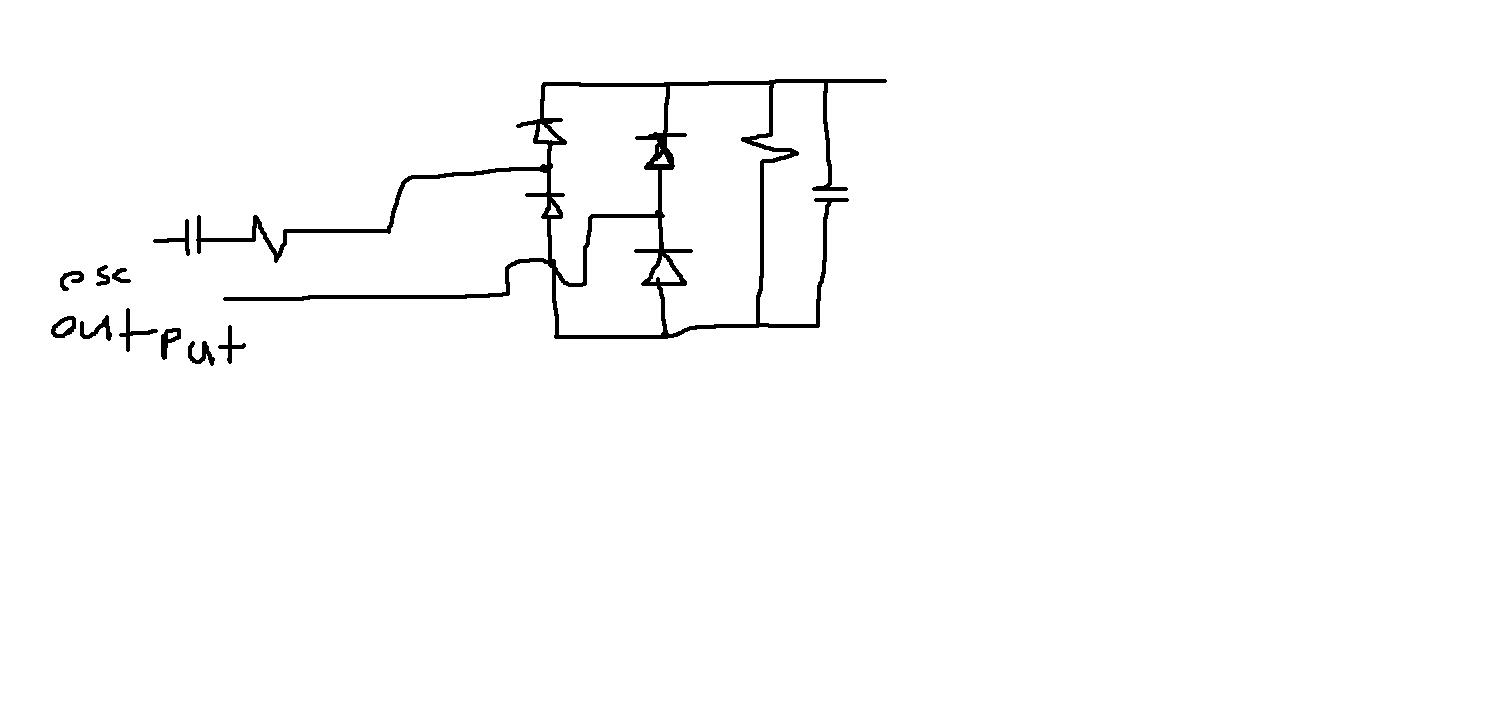
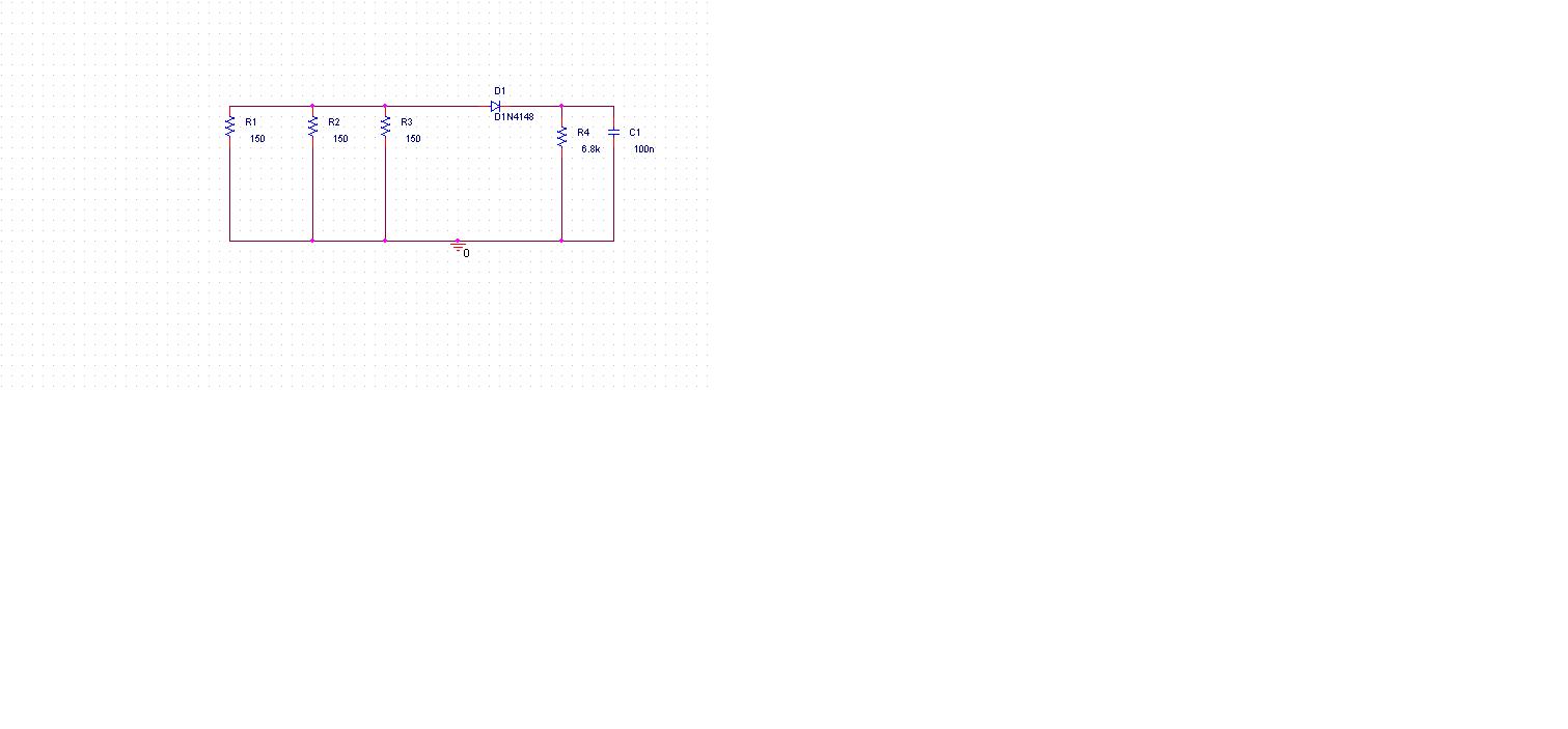
Finally, here is my low level AM transmitter,

Both of you experts, kindly review throughly this circuit, values of components, value of power supply, everything, because I am going to use this as my project.
- - - Updated - - -
Transistor,
For modulator section: BC548
For oscillator section: 2N3904
For RF amplifier : BF459
Are these right transistors?
")