Continue to Site

Welcome to EDAboard.com

Welcome to our site! EDAboard.com is an international Electronics Discussion Forum focused on EDA software, circuits, schematics, books, theory, papers, asic, pld, 8051, DSP, Network, RF, Analog Design, PCB, Service Manuals... and a whole lot more! To participate you need to register. Registration is free. Click here to register now.

Low level AM Transmitter Circuit and little description.

Status
Not open for further replies.
hehe , i confused you sorry..
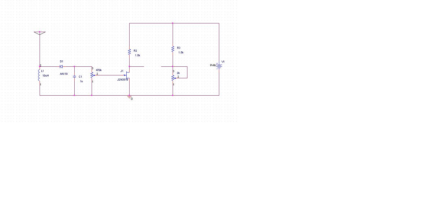
if your oscilator oscilates at 3.5 Mhz than we say that the 3.5 Mhz is the carrier ("it carries the information") , or the modulated signal. If you put a signal at the input of the modulator , for exemple a amplifier and a microphone and you talk to it, that signal (your voice :grin: ) will be the modulator signal ("the information") since it modulates (in amplidude in this case) the 3.5 mhz signal
 
  • Like
Reactions: Eshal

    Eshal

    Points: 2
    Helpful Answer Positive Rating
So you mean, 3.5MHz can be carrier signal (also known as modulated signal) if oscillator oscillates with this frequency.

It can be modulating signal too. Is it are you saying?

If I am wrong then kindly correct me.
 

the signal that is given by the local oscillator is the carier , and the signal that modulates this signal is the modulator signal (the useful signal that you want to transmit, the information).
For example the transmitter from the picture in my previous replays has an oscillator that can oscillate from 0.5 to 50 MHz, and has an other oscilator runing at 1 KHz. The first oscillator that can generate 0.5 to 50 MHz produces the carrier (modulated signal), and the 2 nd oscillator produces the modulator signal. I use a oscilator to produce the modulator signal of 1 KHz, since i do not want to speak all day to the microphone . (I used the generator when reparing radios, or when changing their reciving bands)

Ps : on the upper part of the photo you can see the bord of a frequency meter. That frequency meter shoves me the frequency of my local oscilator (selectable in the range of 0.5 to 50 MHz as i sed) , the actual frequency that i am transmitting on my 1 Khz signal to all the recivers around the area :grin:
 
Last edited:

OK OK.. Now I understand something.
So the transmitter in the picture,here,

has exactly same diagram as you made for your own?

And is it low level? because it has 15v supply. Am I right?
 

yes, the circuit is the part that you need from the picture , i checked the drawing as i sed , it is ok
it is low level

Ps : when you judge something electrical of beeing low or high level it is beter to see the energetical part, generally you need to consider the 'power' not only voltage level or the current by itself . For example : in dc, 100W power can be "made of" 10 V and 10 A , or by 100 V and 1 A , and it is still the same 100W
In RF it is a little diferent .....,you can still empirically judge like this : if my power suply can provide x W power than my consumer can not take more than x W (if your dc power supply has 15V and can provide 1 A current , which means 15 W , then the transmitter can not develop more than 15 W , only less then 15 W)
 
Last edited:
  • Like
Reactions: Eshal

    Eshal

    Points: 2
    Helpful Answer Positive Rating
OK thank you zsolt1. So I am giving this circuit to my teacher. And I am very thankful to goldsmith and especially you zsolt1.

Always be there when I need any kind of help.
 

;-)
ask him how the oscillator works , hehe .. just kidding don't do that . Even i can not explain myself why does that oscillator work , since i can not clearly se the feedbeck loop , the only possible explication would be the magnetical coupling between the coils... (actually i never bothered, i built the circuit and used it)
any way it is simple to replace that oscillator with any colpitts oscillator from the internet , or better from this forum ... so it is not a problem
 

Hi Zsolt1
Even i can not explain myself why does that oscillator work , since i can not clearly se the feedbeck loop , the only possible explication would be the magnetical coupling between the coils
If your mean is your circuit , i can predict how it does oscillate ! :grin:
the amplifier is CE it means to provide positive feed back you will need a phase shifter by 180 degree . L and C that you have used can create enough phase shift thus you will have positive feed back . and thus your circuit will be unstable .
Question : can you check the out put voltage from collector , please ? ( with oscilloscope ?) i think the amplitude will be higher if you get it from collector not base node .
With my best wishes
Goldsmith :smile:
 

hi,
i will pst the oscillogram saturday .... (i am not at home again, from monday to fryday i change my residence because i go to work in an other city) , i am curious to :smile:
 

Hi goldsmith!

Is zsolt1's circuit a good choice to give as a project to my teacher?
 

Hi Zsolt1
I think you have made some mistakes in drawing . i'm sure it's oscillator section has problem . can you re check it please ?
Hi Eshal
I think if he correct it's oscillator section thus it can be used as your project !
( after a hard day i'm here . perhaps tonight i will have more time to spend on your project . and of course equipments that i have promised .
Best Wishes
Goldsmith
 

hi,
just use an other oscillator from the net until things come right....
osc.JPG
there are so many schematics ....
until saturday i can do nothing regarding this theme, as i sed i am not at home .....
Ps: i know for shore that my drawing is identical with the circuit from the photo

Eshal,
you can use the circuit, but i suggest to come out with something that comes more frome you, do not be afraid from in-success, it is normal to make mistakes...beside that we are hier on this forum to help. The circuit was meant to be just a suggestion for you in order to see a principle in it , so try to make something better from that (i am promoting inovation & pioneering here .. hehe :lol: ). For example you could start from the discussed circuit and optimize it :
- how can i make it with less components in order to make it cheeaper and esier to build ?
- how can i modify the topology of the circuit to get the more out of the principle ?
- which parts can i improve in order to .... ?
- which parts can i eliminate ?
- what type of oscillator suits the best the project ? (in order to say to your teacher that : I choosed the x oscilator type because of the following advantages ...... I incrased it's range by .....I ....)
I hope you understand my advice i tryed to give
 
Last edited:

@ zsolt1
Hi, how are you friend? :)
So, in your given circuit, oscillator can be replaced with the Hartley oscillator which is shown in post#112?
If so, then values of components of the oscillator of post#112 are correct?

@ goldsmith
Can I replace the oscillator in the circuit diagram of zsolt1 with the above one, posted in post#112?

Components' values are as it is?
 

they are correct values , how would you change it's frequency from 1,5 to 3.5 MHz ?
which type of oscillator suits the best the project ? colpitts or hartley ? (knowing that you want amplitude modulation not frequency modulation, so a stable frequency is preferred) :?:
 
Last edited:

Here is what I try to do.
Capture.JPG
Please tell me how to connect modulator section and oscillator section, both section has different power supplies.

According to zsolt1's circuit diagram, whole circuit has +15v supply. But zsolt1 said to replace oscillator of the circuit with modified Hartley oscillator (post#112) so it has +12v supply, how to connect these two stages?
:-(
 

Like this?

Capture.JPG

And please tell me should I place a capacitor between modulator and oscillator? (I drawn that with blue color, tell me the value of that capacitor)

Similarly please tell me the values of components of oscillator. (I question marked with orange in color)
 

Hi Eshal
Why this oscillator ? i think this arrangement will be a bit hard to design for you , unless we give you values . and about that capacitor that you told no you shouldn't put that !
 

the values from post 112 are ok.
If you put that capacitor there, no dc will pass, so the oscilator is not suplied.
Ps; the 330 ohm rezistor and the 0.1 uf capacitor is not necessary needed ,it is a RC low pass filter & the 330 ohm limits dc current
 
Last edited:

the values from post 112 are ok.
of course those are ok , but i think it needs more current amplification because of lowest current of that oscillator .
By the way , as i promised , here first circuit comes ! a simple radiation meter ! see below , please :

a mili ammeter will be connected between drain and common node of it's front ! but drain should be into it's positive head .
Best Wishes
Goldsmith

- - - Updated - - -

By the way value of inductor and capacitor are not correct . capacitor should be between 100 pf up to 470 pf . and inductor will given by : 8 turn wire ( 1mm ) on diagonal of 5 mm . it will work for FM band . but for other frequencies it should be increased ( for lower frequencies )
 

Status
Not open for further replies.

Part and Inventory Search

Welcome to EDABoard.com

Sponsor

Back
Top