Continue to Site

Welcome to EDAboard.com

Welcome to our site! EDAboard.com is an international Electronics Discussion Forum focused on EDA software, circuits, schematics, books, theory, papers, asic, pld, 8051, DSP, Network, RF, Analog Design, PCB, Service Manuals... and a whole lot more! To participate you need to register. Registration is free. Click here to register now.

Limiting LNA's current

Squirtle

Junior Member level 2
Joined
Aug 24, 2021
Messages
23
Helped
0
Reputation
0
Reaction score
1
Trophy points
3
Activity points
305
Hello guys,

We are designing multicouplers which consist of LNA, power divider and cavity filter. When LNA is connected before filter, it usually fails, the amplifier PSA4-5043 breaks down. The reason of failing might be presence of too much of other band's signals in the area which cause LNA to drive more current because i noticed that when i applied higher power to the i/p of LNA, it drives more current so if i put current limiter to the DC bias of LNA, maybe i can stop it from breaks down. Deos it work? and if i put power limiter before amplifier, can i prevent it from drawing more current?

Thanks,
 
Current Limiting "may" resolve your breaking-down problem but it does not conclude the main problem of interference by other aggressor signals.
You have to rescue the LNA all before. LNA can work but it will be victim of the other interference signals.
My opinion is to use a filter to eliminate those signals first then protect the LNA.
 
When LNA is connected before filter, it usually fails, the amplifier PSA4-5043 breaks down.
Did you insert the required DC blocking capacitor between the input and the amplifier?

DC_block_required.png
 
The problem is when the filter(helical) is placed before LNA, the signal distorts because before multicoupler, the customer use the one more external cavity filter (I don't know why). Therefore multicoupler's filter and external filter are cascaded and this cause distortion of signal (Certain length of cable needs to be used to prevent distortion). That's why we placed LNA first then helical filter second. In this case signal's shape is as it should be. Is it possible to place something between two filters to fix signal shape?
--- Updated ---

Did you insert the required DC blocking capacitor between the input and the amplifier?

View attachment 186171
Yes, i used the recommended circuit diagram mini-circuit provides
 
The problem is when the filter(helical) is placed before LNA, the signal distorts because before multicoupler, the customer use the one more external cavity filter (I don't know why). Therefore multicoupler's filter and external filter are cascaded and this cause distortion of signal (Certain length of cable needs to be used to prevent distortion). That's why we placed LNA first then helical filter second. In this case signal's shape is as it should be. Is it possible to place something between two filters to fix signal shape?
--- Updated ---


Yes, i used the recommended circuit diagram mini-circuit provides
To my understanding, the LNA oscillates due to mismatching between LNA and Helical Filter. Otherwise a passive component cannot create a distorted signal.
Have you ever measured your LNA and Helical Filter with an accurate VNA ? I believe there is a particular mismatch between LNA and filter.
 
Place a resistor in series with output inductor L1 and may solve the problem (fig. 2, datasheet).
The resistor value could be between 5 ohms and 50 ohms.
The OIP3 may decrease a bit, but should be fine..
 
Place a resistor in series with output inductor L1 and may solve the problem (fig. 2, datasheet).
The resistor value could be between 5 ohms and 50 ohms.
The OIP3 may decrease a bit, but should be fine..
If i place 10 ohms resistor, how can i calculate voltage drop between resistor terminals since the amplifier will not work at 5V anymore and current drawing will not be same.
--- Updated ---

To my understanding, the LNA oscillates due to mismatching between LNA and Helical Filter. Otherwise a passive component cannot create a distorted signal.
Have you ever measured your LNA and Helical Filter with an accurate VNA ? I believe there is a particular mismatch between LNA and filter.
But without external cavity filter, LNA and helical filter work fine. Connecting two cavity filters in series cause problem
 
But without external cavity filter, LNA and helical filter work fine. Connecting two cavity filters in series cause problem
Any combination of Source Impedance may cause an oscillation. Neither cavity filter nor helical filter has pure 50 Ohm Input/Output Impedances.
You have to measure what happens when 2 cavity filters are connected in series.
The question is that: What impedance is seen by LNA when two cavity filter are cascaded.
This looks like source pull technique. A combination of impedance can make the LNA to oscillate.
 
when i applied higher power to the i/p of LNA, it drives more current
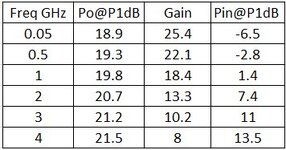
An LNA should work in Class-A, which means that the DC current of the LNA will be independent from the input power.
This is valid in your case if the input power is below Pin@P1dB, according to the table attached.
If you have variations of DC curent vs input power, means the LNA is not in Class-A, your input power is higher than P1dB, and the output signal will be distorted.
The problem of PSA4-5043 is that this amplifier has huge gain variation vs frequency.
Adding a resistor in series with L1 may help to avoid oscillations, but you have to be sure that the input power is always below compression point.
 

Attachments

  • p1db.jpg
    p1db.jpg
    22.8 KB · Views: 80
But without external cavity filter, LNA and helical filter work fine. Connecting two cavity filters in series cause problem
Maybe the reason is a change of reflection phase which causes instability. As a test, you can try to add some length of line between filter and LNA input, to change the phase of out-of-band reflections seen by LNA input.

Another test: You can try to insert a small attenuator, maybe 2dB or 3dB, which doesn't change the input signals too much but might be enough to bring the impedance seen by the LNA closer to 50 Ohm.
 
One additional information; when i connect isolator between two filters, signal shape improves. Therefore either i need to connect isolator between filters or need a certain length of cable.
 

LaTeX Commands Quick-Menu:

Part and Inventory Search

Welcome to EDABoard.com

Sponsor

Back
Top