Continue to Site

Welcome to EDAboard.com

Welcome to our site! EDAboard.com is an international Electronics Discussion Forum focused on EDA software, circuits, schematics, books, theory, papers, asic, pld, 8051, DSP, Network, RF, Analog Design, PCB, Service Manuals... and a whole lot more! To participate you need to register. Registration is free. Click here to register now.

Drop in DC current in Class AB amplifier

arwen16

Junior Member level 3
Joined
Sep 3, 2023
Messages
26
Helped
0
Reputation
0
Reaction score
1
Trophy points
3
Activity points
197
Hello,

I have designed a broadband (0.8-3 GHz) medium power class AB power amplifier. While I was nothing down the output power for different values of input power (-20 to 20dB) for each frequency , I noticed that the current would drop from 78mA to 50mA when I increased the input power. For some frequencies, it would end up increasing from 78mA to 85mA.

I do not understand this phenomenon. Could someone explain what is happening here?
 
Hi,

your values have no meaning for as as long as we don´t see your design.

We don´t even know what load you use.

At these frequencies you may have reflections, resonances and so on that let the current move up and down.

Klaus
 
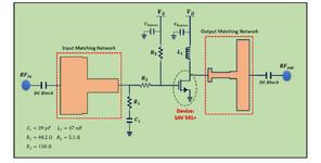
This is the circuit. I used SRFT to design the matching network. Load pull simulation was done for each frequency to obtain the load and was around 24+3j ohms in the band.
 

Attachments

  • Screenshot_20240212-235355.png
    Screenshot_20240212-235355.png
    449.6 KB · Views: 44
HI,

I don´t think it´s Class AB. But I´m no expert in RF design.

In the NF world a class AB amplifier needs at least two transistors.

Klasu
 
In RF amplifier techniques, single transistor "class SB" output stages are commonly known. These are amplifiers with bias current and linear (class A) operation up to a certain power level. Above this level, transistor current is clipped at zero. Assuming linear transistor V/I characteristic, we would expect rising average DC current in class B range. Current is also soft clipped at maximum due to saturation, causing opposite behavior. Actual characteristic is however non-linear, so real behaviour is more complicated. Also varying impedance of output matching circuit can make the behavior frequency dependent.

A nonlinear broadband amplifier is more or less impossible. It generates harmonics, therefore output signal spectrum is different from Iinput. Typically single transistor AB amplifiers use a resonant tank and are not broadband.
--- Updated ---

Two images copied from Steve C. Cripps,
Advanced Techniques in RF Power
Amplifier Design
illustrating class AB behaviour:

1000003520.jpg


1000003522.jpg
 
Last edited:
It seems related to Output Matching Circuit. This circuit transfers an amount of current well to the load at some frequencies, it cannot transfer at some other frequencies.
Therefore average current shows some differences for some of them. There might also be poor harmonic rejection and badly designed supply branch.
0.8-3GHz is already a pretty wide bandwidth so expecting same performance or behavior may cause a disappointment.
You should check out harmonic currents through output matching circuit and get an idea about the efficiency of output matching circuit.
 
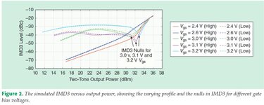
The PA's IMD3 level, using two-tone or modulated signal (especially in class-AB amplifiers) have so named "sweet spots" in their characteristic vs output power.
This may the reason getting various (up and down) collector/drain currents when sweep the output power.
Harmonic frequencies (and the PA load at those frequencies) play an important role of the IMD3 levels.
 

Attachments

  • sweet.jpg
    sweet.jpg
    47.7 KB · Views: 31

LaTeX Commands Quick-Menu:

Part and Inventory Search

Welcome to EDABoard.com

Sponsor

Back
Top