picgak
Advanced Member level 1
Hi Fragrance,
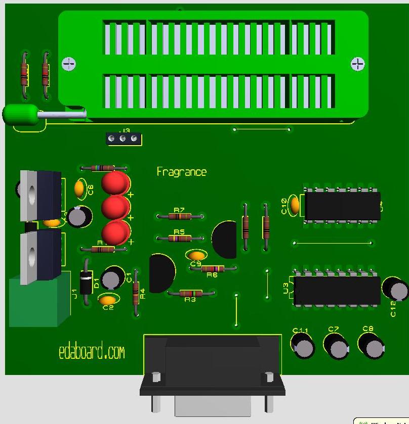
Thank you, here is the link to Picpgm http://picpgm.picprojects.net/software.html Kindly check and provide the settings for your hardware.and please tell the use of J3 connector.
Thanking you
Regards ani
Thank you, here is the link to Picpgm http://picpgm.picprojects.net/software.html Kindly check and provide the settings for your hardware.and please tell the use of J3 connector.
Thanking you
Regards ani