Continue to Site

Welcome to EDAboard.com

Welcome to our site! EDAboard.com is an international Electronics Discussion Forum focused on EDA software, circuits, schematics, books, theory, papers, asic, pld, 8051, DSP, Network, RF, Analog Design, PCB, Service Manuals... and a whole lot more! To participate you need to register. Registration is free. Click here to register now.

Inverter (mosfets overheat immediately)

Status
Not open for further replies.

Raees66

Newbie
Joined
Jun 19, 2022
Messages
2
Helped
0
Reputation
0
Reaction score
0
Trophy points
1
Activity points
19
Hi all experts
Can anyone guide me why MOSFETs are getting too hot in inverter. I made a small inverter using tl494 pwm. The oscillation frequency is 50 Khz. I wound ferrite transformer EER35 varying all necessary calculation according to 50Khz frequency. But when I power on, MOSFETs get hot instantly and some time blown off. Interestingly, when I connected another ferrite transformer which wound on 15Khz frequency parameters and set the oscillation frequency if TL494 as 15khz, the MOSFETs works normally and bulb lightup fully
What is the problem. Can any one expert advise me in the matter.
 

Hi,

so basically when an electronics device get too hot it is because:
* too much heat generation
* bad heat spreading
from your informations we know nothing about both of them.

generated heat in a MOSFET:
* conduction loss
* switching loss
* diode loss

conduction loss maybe caused by too high current.
Too high current maybe caused by
* inductor saturation
* not sufficient dead time
* not sufficient gate drive level

switching loss:
* not sufficient gate drive current
* slow diode (trr)
* ringing / bad PCB layout

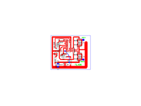
If you want to give detailed help we need detailed informations first:
* schematic
* PCB layout
* your transformer calculations

No textual descriprion can replace these informations. Please give them all in your next post.

Klaus
 

I used TL494 pwm. Set the frequency 50khz. I use ferrite transformer EER35. Ae = 1.10 cm square. I set the Bmax 1800 G.
Primary 3+3 turns. ( Wire dia 1.41mm, I used litz wires 0.5mm x 8). For load up to 200w.

Secondary 78 turns using 0.36mm dia wire.
IRF3205 MOSFETs =4 (two parallel each side).
 

Attachments

  • TL494 PWM.png
    TL494 PWM.png
    7.1 KB · Views: 115

Hi,

I recommend to read some application notes about switch mode power supply PCB design.
Many semiconductor manufacturer provides them for free, because it is important.

In short:
The PCB layout, especially for power switch mode supplies, has big influence on overall performance.
If done correct, then the circuit may worke precisely with low heat generation and low noise emmissions.
If done wrong it may lead to oscillations, heat, short lifetime, overheat,

Simply eletcrically joining the parts does not work.

Klaus
 

I see no mention of heat sink, the larger thermal path or
cooling airflow. Every inverter I've had, had a fan and a
finned case.

It's not clear whether the short-term heat ramp and damage
are related to inrush current / filter charging, and would
stabilize if these are less severe, or if it's more about
heinous switching losses (which, given old school control
and gate drive (unoptimized?) are reasonable to expect.

And if you're saturating the inductor/xfmr (at such low chop
freq, expect ind/xfmr to be large) you can forget about
surviving.
 

Status
Not open for further replies.

Similar threads

Part and Inventory Search

Welcome to EDABoard.com

Sponsor

Back
Top