Continue to Site
Follow along with the video below to see how to install our site as a web app on your home screen.
Note: This feature may not be available in some browsers.
 www.partsim.com
please, can you say what do you mean" using LM348 component without simulation model."Looks like you are reproducing the problem you produced in PSpice before. Using a LM348 component without simulation model.
Hi,
Additionally
* no feedback of U2
* positive feedback of U4, U5
* wrong power supply polarity of U3, U1A, B2
* U1A at all
* some part values
* no power supply decoupling capacitors
make no sense.
Klaus
Just read the warning thoroughly and follow the suggestion: Use a symbol from the PSpice simulation library. Orcad schematic entry is used for simulation and PCB design. Most libraries are for PCB design only, they have associated footprints but no SPICE model. The other option is to download the missing model from the internet and attach it to the symbol.please, can you say what do you mean" using LM348 component without simulation model."
Yes, that's what KlausST adressed in post #11.surely this is an error - should be a unity gain buffer ?
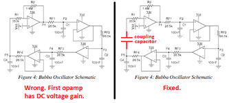
The wrong bias voltage can be still found at TI website. https://www.ti.com/lit/pdf/slyt164 See Fig.11.Here is another wrong circuit from Texas that I got my wrong idea from:
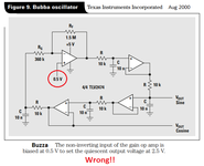
They didn't think.I wonder why they selected an output from the fairly high impedance RC filter instead the very low impedance from the output of the opamp filter buffer?