AHMED SALLAM
Newbie
hello
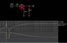
i have shunt fed Hartley osc circuit the out is Nosie help me to modify the out signal

i have shunt fed Hartley osc circuit the out is Nosie help me to modify the out signal
Follow along with the video below to see how to install our site as a web app on your home screen.
Note: This feature may not be available in some browsers.
Harley type contains a coupled inductor. Is this done in your schematic (L7 L8)? You may need to customize it in the simulator options. Test the two windings in both directions relative to one another.hello
i have shunt fed Hartley osc circuit the out is Nosie help me to modify the out signal
 R/L = 23 iron core power R/L = 10k leaded wirewound
 R/L = 110k SMD , Compute Q at operating f to make sure it behaves as expected.
to to get harmonic
Did you try a web search before such a brave request?any one give me shunt fed
Hartley oscillator
circuit with real sample components to to get harmonic