Continue to Site

Welcome to EDAboard.com

Welcome to our site! EDAboard.com is an international Electronics Discussion Forum focused on EDA software, circuits, schematics, books, theory, papers, asic, pld, 8051, DSP, Network, RF, Analog Design, PCB, Service Manuals... and a whole lot more! To participate you need to register. Registration is free. Click here to register now.

How to measure Bandwidth and Q of high-pass T-match circuit?

Status
Not open for further replies.

VINAY_RAO

Junior Member level 2
Joined
Jul 24, 2009
Messages
22
Helped
0
Reputation
0
Reaction score
0
Trophy points
1,281
Location
IITG
Activity points
1,510
Hello all,

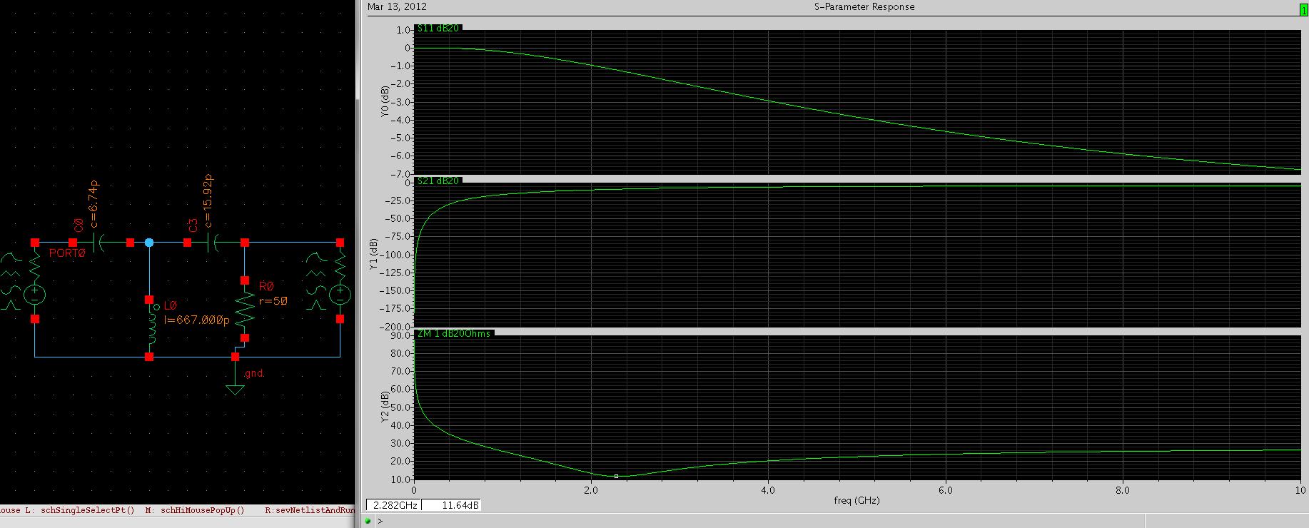
Here I attached the circuit and dB plots of its S11, S21 and ZM1. I designed this circuit for fr (center freq/resonating freq) =2.4GHz and Q = 5. From theoretical concept, I am calculating Bandwidth as
B.W = (fr/Q) = 480MHz.
How can I measure simulated Bandwidth and Q from the plot which I attached for the given T-match circuit?


Regards,
Vinay Rao.
 

I dont know why are you measuring the BW from Q. Usually we measure BW from S21 and then calculate the Q of the circuit. Your filter seems to be high pass filter and high pass filter usually have cut off frequency rather than of BW.
 

Hello capcas,
Thanks for your reply. Yes it is high pass filter. What i defined "B.W = (fr/Q)" is one of the definition of Q. I designed this circuit for Q=5. How can i measure resulted Q from the simulation plot? For high pass, i have to measure cut-off frequency and then i got to find out 'Q' you mean?
 

Usually for high pass and low pass filter you measure Q by the rejection it provides, please look at Microwave Engineering by Pozar. In this circuit you are getting almost infinite Q because of ideal nature of selected elements.
 

Status
Not open for further replies.

Part and Inventory Search

Welcome to EDABoard.com

Sponsor

Back
Top