Continue to Site

Welcome to EDAboard.com

Welcome to our site! EDAboard.com is an international Electronics Discussion Forum focused on EDA software, circuits, schematics, books, theory, papers, asic, pld, 8051, DSP, Network, RF, Analog Design, PCB, Service Manuals... and a whole lot more! To participate you need to register. Registration is free. Click here to register now.

How do I read this transformer datasheet?

Status
Not open for further replies.
The bobbin, core and coils came today. I bought half cores which fit into the bobbin but I should have bought full core, it isn't a problem for test pieces though, I just want to learn what to do. The wire I bought is 0.2, 0.3, 0.4, 0.5 and 0.8mm squared. The 0.8mm is hard to wire, so I think it'd be best to use the 0.5 and below. I have a few questions, is it better to wire the coils next to each other or on top of each other? Should I glue the core top down or bottom up?

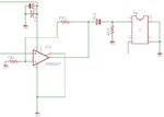
Choosing the values of inductance for each coil is difficult. I've attached the circuit I'm using. Essentially the output from an opamp is AC coupled and this fed into the transformer to be made, the load is a piezo.

The task is to wire the transformer to give maximum power transfer. The AC coupling capacitor is 10uF and low ESR. The piezo is 1nF and operates at its resonante frequency of 40KHZ, its impedance is unknown. The wiring ratio isn't critical but I'm targetting 1:5. I have tested an existing transformer with different added capacitance to the piezo load and in some circumstances it does help power transfer as mentioned earlier in the thread. The opamp (OPA 548 ) also mentions that an RC network on the load also helps with stability for capacitive loads. It suggests 10nF-100nF and 3-10 ohms.

I've done some numbers. The capacitive load should be the piezo plus 10nF for stability = 11nF
With a wiring ratio of 1:5 the capacitance reflected back to the primary coil will be 11nF x 25 = 275nF
At resonance of 40KHz the tank inductance of 275nF is about 60uH.
This implies the secondary coil is around 1500uH

Do the numbers look ok? Any suggestions welcome.

Thanks,

Ant.
 

Attachments

  • circuit.jpg
    circuit.jpg
    38 KB · Views: 97
  • opa548.pdf
    1.5 MB · Views: 73

I have wired it.

Using just one half core left me with very little inductance despite 20 turns, however as I have a second half core putting them together worked better. I found I could alter the inductance quite easily by rotating the second half core. It won't make any difference to power consumption if I left the second core at 90 degrees would it?

The wiring isn't pretty, will messy wiring make much difference? I have a feeling having all of the wires next to each other in neat rows would be better but I'm not sure why.

I used the same thickness wire for both coils, 0.4mm squared, will that be enough for 2A?

I have two conflicting thoughts...1) that the turns ratio determines the inductance ratio via squaring 2) the thickness of the wire affects inductance. So if the primary and secondary coils have different thicknesses the inductance ratio must change...hmmm.

I will test it tomorrow.
 

little point in increasing the leakage inductance by opening up the core (turning it 90 degrees?), should have little impact on power consumption anyway.
temperature rise is dependant on the entire design, the intent being that core loss (relatively constant) should be about the same as the resistive losses in the wire. you may find .4mm wire to be too small, but it sounds like you have a lot of room left on the core to use thicker wire.

the inductance ratio is not dependant on the thickness of the wire, but by the turns ratio.
 
  • Like
Reactions: ants

    ants

    Points: 2
    Helpful Answer Positive Rating
Ants,

You must align the cores and clamp them together. I am not sure which ones you are using but the RM and ETD cores have spring clips to clamp the two halves.

As already said, it is the turns that determine inductance, not wire diameter.

Are you sure the 0.4 wire is area not diameter?

Keith
 

Thanks for the comments. The markings on the wire reels are confusing/wrong. For example they say 0.4mm2 implying the cross sectional area is 0.4mm2. But I just measured it and the diameter is 0.4mm so the area will be ~ 0.125mm2.

I bought two RM6 bobbins/cores, they were given different names so I thought I was getting 2 slightly different ones but they are the same. I will make up the second one, I didn't get any clips to clamp the cores but I know the principle now so a bit of glue will suffice when I'm done.
 

Don't glue it - you will create a gap. Gaps are important in transformers but only if you design for them. The inductance will change. Wrap some tape round the cores until you get the clips.

Keith
 
  • Like
Reactions: ants

    ants

    Points: 2
    Helpful Answer Positive Rating
I've taped the half cores together, untaped with the cores resting against each other I had 60uH on the primary, taped I have 100uH. By pressing the cores together the inductance changes. I will need the clips, I will also get some full cores to test. I have tried it and it works in that the secondary ups the voltage as expected. I haven't had a chance to test it with my piezo yet, perhaps 100uH for the primary coil will be too far away from target.

Thanks,

Ant.
 

Yes, I think the core Al values are specified with a certain clamping pressure. It clearly makes a difference!

Keith.
 
  • Like
Reactions: ants

    ants

    Points: 2
    Helpful Answer Positive Rating

I reviewed the last contributions and would like to add some remarks.
The piezo is 1nF and operates at its resonante frequency of 40KHZ, its impedance is unknown.
I agree, that it's unknown, as long as you don't try to measure it. But I don't know why.

Generally, I keep my opinion, that the transformer design should be based on determining the transducer impedance.
The capacitive load should be the piezo plus 10nF for stability = 11nF
I don't understand the purpose of adding a parallel capacitor.
I found I could alter the inductance quite easily by rotating the second half core. It won't make any difference to power consumption if I left the second core at 90 degrees would it?
If you are reducing the core area, the saturation flux will be reduced, too. I don't know, if you calculated the core flux at all. If the core is operated at high flux values or even saturated, losses will be surely affected.
 
  • Like
Reactions: ants

    ants

    Points: 2
    Helpful Answer Positive Rating
Hi FvM,

Thanks for your comments, they are helpful.

I agree, that it's unknown, as long as you don't try to measure it. But I don't know why.

I would like to estimate the impedance. I can recall some time ago you helped me determine the power consumption of the transformer I'm now replacing, it involved placing a 1 ohm resistor in series with the primary coil and measuring the voltage across it to determine the current (at resonance with the load). I'm thinking I could do this again?

Generally, I keep my opinion, that the transformer design should be based on determining the transducer impedance.

I think you are right. The datasheet mentions adding an RC network helps with stability for capacitive and inductive loads. It will probably be ok without one.

If you are reducing the core area, the saturation flux will be reduced, too. I don't know, if you calculated the core flux at all. If the core is operated at high flux values or even saturated, losses will be surely affected.

I wouldn't know how to calculate the saturation/core flux or if it would be an issue? I have ordred some new bobbins to test, both of the ones I bought broke. I think it would be better to leave the core closed and I've ordered some clips to keep cores clamped.

Thanks,

Ant.
 

I have built another transformer and tested it with a more user friendly piezo. The piezo has a resonant frequency of 138KHz and a static capacitance of 2.05nF.

The turns ratio was 1:3. I targetted a primary inductance of 72uH, this combined with 2.05 x 9 = 18.5nF gives an LC circuit at 138KHz. As it happened 4.5 turns on the coil was 75uH so I thought that is ok, by the time I'd wound the secondary coil and soldered the pins it was up to 90uH. I wound the coils around the pins which added a fair bit, it hadn't occured to me that would happen.

My question is how important is accurately making the transformer, should I rebuild the transformer with 72uH primary?

And how can I get the 'cleanest' signal? The piezo has a fair bit of noise whether it is mounted or not.

I tested the piezo with and without the transformer to estimate its impedance, it appears to be around 22 ohms. The odd thing about the testing is that I seemed to get around the same volts on the piezo with and without the transformer. The difference was with the transformer I was getting 7V and 450mA without 7V and 150mA. This could be some kind of tuning error, I need to test more.
 

If the piezo impedance is 20 ohm, it would be transformed to 2.2 ohm at primary side. The value may be below the optimal load impedance of your amplifier.

Another point to consider is transformer leak inductance.

From the data you mentioned (AL ≈ 3700 nH/n²), I conclude that you have built the transformer with an ungapped core. But it's inductance will be rather unstable, affected by temperature variations and signal level. It's not a good way to build a resonant circuit.
 
  • Like
Reactions: ants

    ants

    Points: 2
    Helpful Answer Positive Rating
Hi,

What is a gapped and ungapped transformer core?

I built the transformer with the RM6 and 2 half cores from the website below, it was clipped together. The AL seems to be 2400nH, I don't actually know what that is. After testing I'd say the resonant circuit wasn't good, it does work but I'd prefer a better signal.

I will be making another transformer, this time for the 41KHz piezo I mentioned earlier.

What would you recommend? Should I stick with this RM6 and these cores? I will also target the primary inductance more closely. I wouldn't know how to estimate leakage.

I have checked the datasheet for the opa548 opamp, it doesn't mention an optimal impedance.

FERROXCUBE|CSV-RM6S-1S-6P-G|BOBBIN, RM6S, 1 SECTION, 6PIN | Farnell United Kingdom

EPCOS|B65807JR87|FERRITE CORE, HALF, RM6, N87 | Farnell United Kingdom

Thanks,

Ant.
 

Attachments

  • opa548.pdf
    1.5 MB · Views: 59

A gapped core has a small gap in the centre, usually up to 1mm, which allows the core to store more energy without saturating (I hope that is an accurate description). It drops the Al considerably, down to maybe 100nH/turn squared for 1mm. It is an important design tool for high power transformers. An alternative is the iron powder cores from Micrometals which have low Al and high saturation levels without a gap.

Keith
 
  • Like
Reactions: ants

    ants

    Points: 2
    Helpful Answer Positive Rating
I see. Yes the transformer I made is ungapped and I'd need a gapped core with more turns to improve accuracy.

Thanks,

Ant.
 

I'd need a gapped core with more turns to improve accuracy
Yes, if you need to achieve a stable resonance frequency. A regular transformer would be designed with high (main) inductance to reduce the reactive current and use an ungapped core. As Keith explained, the air gap would be used to store more energy, e.g. for a flyback transformer. Or making the transformer part of a resonant circuit.

The core has an AL value of 2400 according to the catalog, Epcos Ferrite design tool however gives a value of 3500, which apparently better fits your measurents.
You mentioned in a previous post, that you are using "half" windings to adjust the inductance. The bad thing with this "trick" is, that it considerably increases the leak inductance of the transformer, and at worst case, brings up partial core saturation. So you better don't do it.

I have checked the datasheet for the opa548 opamp, it doesn't mention an optimal impedance.
Right. It's not strictly depending on the OP rather than power supply conditions etc. But you surely can imagine, that you'll get maximum output power at a certain output load and less power at higher or lower load impedance. In any case, you get maximum output power, when you tune the circuit, respectively the generator frequency, to achieve a pure resistive load at the OP output.


The flux of 200 mT specified in the datasheet is achieved by 0.2 * 36.6 e-6 * 6.28 * 40e3 = 1.84 Vpeak/winding at 40 kHz. So operation down to this frequency should be no problem with 4 or 5 windings at the primary.
 
  • Like
Reactions: ants

    ants

    Points: 2
    Helpful Answer Positive Rating
You mentioned in a previous post, that you are using "half" windings to adjust the inductance. The bad thing with this "trick" is, that it considerably increases the leak inductance of the transformer, and at worst case, brings up partial core saturation. So you better don't do it.

This makes sense. If I use a gapped core it will be easier to get close to the target inductance with full windings.

It's not strictly depending on the OP rather than power supply conditions etc. But you surely can imagine, that you'll get maximum output power at a certain output load and less power at higher or lower load impedance.

I know for example audio amps usually require 4 or 8 ohms for maximum power transfer. With this transformer I tried to ensure that the piezo capacitance was reflected back to the primary coil to achieve resonance and essentially cancel the primary inductance out. So I would be left with the 2 ohms 'resistive' as mentioned earlier. It is hard for me to grasp what would be the best load impedance for the amp. The power was around 1.5W from V²/R (36/22) using the 22 ohms but 18W using 2 ohms. This is the difficult bit.

In any case, you get maximum output power, when you tune the circuit, respectively the generator frequency, to achieve a pure resistive load at the OP output.

I understand that I need to tune the piezo.

The flux of 200 mT specified in the datasheet is achieved by 0.2 * 36.6 e-6 * 6.28 * 40e3 = 1.84 Vpeak/winding at 40 kHz. So operation down to this frequency should be no problem with 4 or 5 windings at the primary.

It looks like if I wanted to put say 30V across the primary it would cause a problem. What exactly would happen?

Thanks,

Ant.
 

It looks like if I wanted to put say 30V across the primary it would cause a problem. What exactly would happen?
At the saturation flux (about 400 mT, double of the caculated value), the transformer voltage will be effectively shorted. But you will face considerable core losses before. There are diagrams in the EPOS datasheets showing core losses versus frequency and flux.
 
  • Like
Reactions: ants

    ants

    Points: 2
    Helpful Answer Positive Rating
Thanks.

One other thing. What is the formula to calculate Vp/winding?

It looks to be Vp= mT * Frequency *Ae *XYZ

It is the final term I can't place.

Ant.
 

Status
Not open for further replies.

Similar threads

Part and Inventory Search

Welcome to EDABoard.com

Sponsor

Back
Top