Continue to Site

Welcome to EDAboard.com

Welcome to our site! EDAboard.com is an international Electronics Discussion Forum focused on EDA software, circuits, schematics, books, theory, papers, asic, pld, 8051, DSP, Network, RF, Analog Design, PCB, Service Manuals... and a whole lot more! To participate you need to register. Registration is free. Click here to register now.

Transformer

Toni rodrigo

Newbie
Joined
Dec 3, 2023
Messages
4
Helped
0
Reputation
0
Reaction score
0
Trophy points
1
Activity points
35
Hey everyone :)
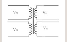
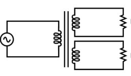
for my finaI project in the university I nneed a transformer like something in the picture that I attach.
1 or 2 windings in primary and 2 windings in secondary.
I want to work with the transfoemer with sine wave at frequency of 30Khz.
Voltage:5V
Max Current:1A
ratio: 1:1:1:1
I need something like 1 "input" and 2 "outputs"
I didn't find something that I can buy in the internet
Thank you very much
 

Attachments

  • Screenshot_20231205_003037_Chrome.jpg
    Screenshot_20231205_003037_Chrome.jpg
    52.5 KB · Views: 42
  • Screenshot_20231205_003148_Google.jpg
    Screenshot_20231205_003148_Google.jpg
    40.1 KB · Views: 42
Tentatively for efficiency windings 300 uH should carry 1A peak at 5VAC 30kHz. (Simulation comparison below.) Notice lower Henry value conveys about 1A but is inefficient because it admits much greater than 1A.
Greater Henry value is inefficient because of reduced current carried.

1:1 is a coupled inductor and that may be a term to search for. Normally transformers are built to step up or down.

You can wind your own custom transformer on a core rated at least 1A saturation.

Transformers 3 compare different primary values 30kHz sine 5VAC.png

--- Updated ---

Link to Falstad's animated interactive simulator. Click it to:
1) Open his website.
2) Load my schematic in the simulator.
3) Run it on your computer.

tinyurl.com/yukc9ajt

Toggle Full Screen (under File menu).
Enlarge scope traces by dragging mouse upward at border of scope region.
 
Last edited:
You should decide on pk or use rms for real power, don't let us guess.
Magnetizing current for coupling may need to be about 10% of real current.
Allow Rs on coils to cause 10% loss at full load for VA rating.
Can you use 1:2 centre tap secondary?

You know how to compute XL(f) right?

5 V / 1 A = 5 Ohm
XL (30 kHz) = 50 Ohm, L = 265 uH
DCR << 5% of 5 Ohms = 250 mohms

This one is not quite big enough for L but is a good starting place to look. $9 at D-K

1701751701908.png


Getting closer using this search method https://www.digikey.com/en/products/filter/specialty-transformers/165

1701752734375.png


You can wind your own or modify this to isolate the secondary. You only need 3 windings and 6 pins , but your configuration is uncommon.

but it meets my specs. 1:1:1

L p1-2 : 269 uH vs spec 265 uH
DCR 150 , 200 mohms vs spec 250 mohms max.

1701753243025.png


$172 per 100
 
Last edited:
Hi,

you may try a search on "pulse transformers for IGBTs" (or SCRs).

And yes, it´s not difficult to make your own.


@BradtheRad:
I do not expect the 3mH inductance to directly have influence on the secondary current.
The 3mH should be the inductance for magnetizing the core. This current should be independent of load.
But what influences the secondary current (voltage) is the coupling factor and the stray inductance.
Maybe your simulation uses a fixed % rate for L_Stray/L_Magnetizing?


Klaus
 
But what influences the secondary current (voltage) is the coupling factor and the stray inductance.
Maybe your simulation uses a fixed % rate for L_Stray/L_Magnetizing?
I trust your expert knowledge about the deeper parameters of this topic.
Indeed I reduced the coupling coefficient of the simulated transformers. The default is .999 and it yields performance which lives up to the textbook ideal. However we expect real-world losses in the area of 15%. So I played with one of my previous transformer comparisons which happened to use .995 for the coupling coefficient. That little difference reduces performance.

It tells us about performance when you increase or decrease Henry value. It explains why there's little advantage to a 10X increase, because there's a point where it becomes 'overkill' to wind that many more turns of wire.
 
Hi,

there is loss dou to coupling factor <1.
But there is also winding loss.

And here the higher the Henrys, the more winding turns you need, the more winding resistance you have. Thus higher winding (copper) loss.

I don´t know whether your simulation adjusts winding resistance when you change inductance value. It may do this or not...

***

In a real transformer, if you increase primary henrys you increase winding count .. and you have to also increase secondary winding count to maintain output voltage.

Klaus
 
Hi,

you may try a search on "pulse transformers for IGBTs" (or SCRs).

And yes, it´s not difficult to make your own.


@BradtheRad:
I do not expect the 3mH inductance to directly have influence on the secondary current.
The 3mH should be the inductance for magnetizing the core. This current should be independent of load.
But what influences the secondary current (voltage) is the coupling factor and the stray inductance.
Maybe your simulation uses a fixed % rate for L_Stray/L_Magnetizing?


Klaus
Hey
Thank you about the answer. this is good for continuous signal?
 
You should decide on pk or use rms for real power, don't let us guess.
Magnetizing current for coupling may need to be about 10% of real current.
Allow Rs on coils to cause 10% loss at full load for VA rating.
Can you use 1:2 centre tap secondary?

You know how to compute XL(f) right?

5 V / 1 A = 5 Ohm
XL (30 kHz) = 50 Ohm, L = 265 uH
DCR << 5% of 5 Ohms = 250 mohms

This one is not quite big enough for L but is a good starting place to look. $9 at D-K

View attachment 186672


Getting closer using this search method https://www.digikey.com/en/products/filter/specialty-transformers/165

View attachment 186673

You can wind your own or modify this to isolate the secondary. You only need 3 windings and 6 pins , but your configuration is uncommon.

but it meets my specs. 1:1:1

L p1-2 : 269 uH vs spec 265 uH
DCR 150 , 200 mohms vs spec 250 mohms max.

View attachment 186674

$172 per 100
Thank you very much.
My signal is continuous signal, 30Khz@3V(p-p) (not 5V).
And I think max I(rms) of 0 4A is ok for me
 
Last edited:
It says 24 V-us max which I think is peak voltage * slew rate T so 30 kHz is ? t= 3V/13 us for a triangle current for V*us= 39

The ET (or V-t) Max is calculated to limit the core loss and temperature rise at 200KHz based on a bipolar flux swing of 210mT Peak.
 

LaTeX Commands Quick-Menu:

Similar threads

Part and Inventory Search

Welcome to EDABoard.com

Sponsor

Back
Top