Mansour_M
Full Member level 1
- Joined
- Jul 30, 2006
- Messages
- 99
- Helped
- 11
- Reputation
- 22
- Reaction score
- 3
- Trophy points
- 1,298
- Location
- Newcastle, UK
- Activity points
- 1,944
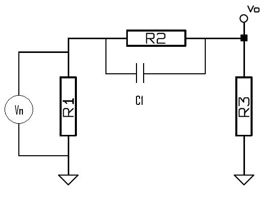
Consider the circuit in the attached picture.
R2 and R3 are noiseless. and V1 = (4*k*T*R1*B)
if C1 was not in the circuit, it would be possible to use the following equation and calculate the output noise voltage.
V0 = R3*V1/(R1 + R2 + R3)
However I do not know how to calculate the output noise if C1 exists.
In the following link, the noise analysis of a RC is explained. In the text a "Brick Wall" technique is described. I have no idea how to use this technique and I could not find any reference for that.
http://jcatsc.com/media/TechnicalReports/17-Noise2.pdf
If any body knows how to calculate the output noise voltage of current, please help me.