Continue to Site

Welcome to EDAboard.com

Welcome to our site! EDAboard.com is an international Electronics Discussion Forum focused on EDA software, circuits, schematics, books, theory, papers, asic, pld, 8051, DSP, Network, RF, Analog Design, PCB, Service Manuals... and a whole lot more! To participate you need to register. Registration is free. Click here to register now.

help with interfacing pic to GSM program

Status
Not open for further replies.
autobauding 16f

umery2k75 said:
even the gsm module are connected internally with just TX and RX and GND.

Who said that to you? If you are correct, then why do Modem manufacturers include those pins?
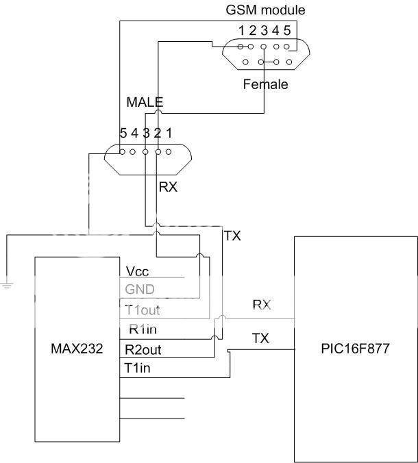
Tell me, can you do some modification, if yes, then do as I said.It would work else I don't know any other way, I have explained you the logic for doing this.You just connect those pins of modem on the DB-9 and that's it.Do the shorting,swaping in the wire.You won't change your circuit, your circuit would be the same except it would have other pins connecting on the DB-9 connector as TX,RX and GND.
Still you'll use only TX,RX for communication.Other pins will be loop back to the Modem, just to fool it,thinking it's talking to another modem.

its in their schematic diagram, the one i bought. BenQ M22 Modem only uses TX RX and GND to communicate. i tested it in the hypertermanal and yes it can send SMS by using only that pin. the MODULE is design by the manufacturer, its has pcb layout already, so changing its pin configuration internally can ruin its design PCB
 

pic y gsm

okay, then make another cable , in that cable just swap TX with RX and RX with TX.It will work.
As far as hyperterminal is considered, wires are connected TX to TX and RX to RX.
For PIC to GSM modem, connect TX with RX and RX with TX and also connect Gnd to Gnd.
 

auto swap tx/rx circuit

oh i notice just now,

remember the schematic diagram of the gsm modem mr emery?

it's included in the kit right and it has a max3222 inside

so its wrong for me to use max232 in my pic circuit right?


all this time im using two max232 O_O


like this


pic curcuit --->max232<------>serial cable<----->max3222<-----gsm modem

thats the flow, oh my god!!!
 

pic to gsm

Try it up.Also one thing more, you have to swap TX with RX and Rx with TX in this case, when communicating GSM with PIC.Otherwise it will not work.
 

gsm modem circuit diagram

if i use TTL logic do i need to make the power suply the same?


i mean if my gsm module have 5v power supply then my pic module should have 5v also?


if in any case if my volategs for the modules are different what would be the problems that may i encounter?

thnx for the continous reply. ty ty
 

sample interfacing code gsm connectivity

So did you get success in doing so?


i mean if my gsm module have 5v power supply then my pic module should have 5v also?

It's not a tumb rule, but mostly controller operates on +5V, there are special condition, when PIC uses +13V on Vpp pin.It need +13V when you do low voltage programming, but it's not necessary.

For the PIC, yes it uses 5V for the operation.I hope this issue of your gets resolve soon.
 

pic to gsm schematic

argz, i dont kn0w what to do.

i tried evrything but it seem it doesnt work at all.

whats wrong with my approach when in fact

my gsm module works on hyperterminal

my pic module works on hyperterminal also

and the pic+gsm module combination works on proteus software.


:cry::cry:
 

schematic diagram of gsm modem

im using wavecom gsm module. i can send sms/make calls using the gsm to other number using hyperterminal. but i hav problem in sending sms or make calls if im using PIC. is all the methods given in previous post can be implemented to this wavecom gsm module?anyone hav any sample codes using C and circuit diagram that can help me in this project?thanks! :)
 

pic programing gsm module

Did you tried to swap the TX with RX and RX with TX?
First you answer this.

Also Pin5(Ground Pin) of PIC must be connected to GSM Modem Pin5(Ground pin).You are at some point, making some mistake, that's why it's not working.

Just don't loose hope, keep on trying.
 

circui interfacing gsm

hi everyone there.. i've got a question here... i'm actually trying to learn more about the PIC... currently i'm interfacing a 16f873a to a gsm modem... the gsm modem is having a baud rate of 115200 and i should use a 20MHz clock for my PIC... does my 16f873a supports the 20MHz clock? thanks for the reply in advance..

i'm still working on the interfacing of the PIC and gsm modem as well...
my connections are actually
RC6(TX) ---> T1IN(MAX232) ---> T1OUT(MAX232) ---> RXD(MODEM)
TXD(MODEM) ---> R1IN(MAX232) ---> R1OUT(MAX232) ---> RC7(RX)

does this work theoritically? i tried experimenting it but it seems not working...
lastly, thanks again!

and btw, do i need to short the rts and cts? could i just leave it as it is? what about the rest of the db9 pins? sorry for my lack of knowledge...

keane
 

gsm interfacing circuit diagrams

@keane

in my PIC16F877 i used 18.432 MHz, dataheet say it's 0% error at 115200 bps

your connections should work, also include the ground

check your modem flow control setting, mostly it's default to "no flow control" so only RX, TX, GND are used other pins are left unconnected
 

rts/cts connected internally

thanks for the reply... but i tried writing the program using 18MHz and also tried with 20MHz... in the program, i simply used the ADC to obtain a temperature from the LM35 and displays on LCD...

it is not working when i'm using the crystal 18Mhz or 20Mhz but it works when i'm using 4MHz... what does this mean? does it mean that my pic16f873a does not support such high crystal frequency? does the capacitor affects?

therefore, i'm unable to set the baudrate of 115200 to communicate with the modem? pls help me here... thank you!

keane
 

found gsm progam

check oscillator configuration setting, should be XT if crystal is greater then 4 MHz

if your programming in assembly, changing oscillator clock needs changing LCD timing codes too

why do you need that high baud? 9600 at 4 Mhz (BRGH = 1) should be enough
 

gsm modem to pic programs

hi!!

As suggested by Mr. Umery2k75,we have made different cable for communicating between PIC & GSM .

Quote:"The cable that you use with GSM module and with Hyper Terminal has no cross over connection, but when GSM module and PIC will be communicating, RTS and CTS pins should be short at the GSM module side, additionally TX and RX must be swap.I have given you the hint, that's the only way your PIC would communicate with GSM module.I myself have wasted so much time in it, until I discovered this remedy"

The only problem while communicating with GSM is that due to network problem it may not gets connected always. So for this we have to recall "ATZ" command during initialization.

And Finally I have successfully sent message to user mobile using GSM through PIC24F. At the same time i can execute any AT command(e.g. calling user,reading message from GSM memory).

Once again Thank you very much Mr.umery2k75!
 

faults in gsm modem pic

Hi everyone,

I also had this problem with module Fargo Maestro 100 GPRS/GSM. But now i can send and receive data between pic16F877 and this module.

First, you must sure that you can tranfer data between PIC and PC
second, you must sure that you can tranfer data between PC and your module GSM.

If it's ok. swap Tx and Rx pin at max232. and try to send data from PIC to module, sometimes it's ok. But it's still not working, you must use DTR pin (pin4 in DB9 of module). Making a change in voltage level at this pin will warn the module that your device is ready(or turn on). Firstly, connect it to the GND then connect it to 12V. The module will response for your command.
 

baud rates for gsm to pic

umery2k75 said:
Thirdly, I haven't read your assembly program, but I must tell you that, there's one more thing which you have to understand and that's the Serial Cable.I have had the similar kind of problem.

The cable by which you interface your GSM module with HyperTerminal is different
The cable by which you interface your GSM module with PIC will be different

The cable that you use with GSM module and with Hyper Terminal has no cross over connection, but when GSM module and PIC will be communicating, RTS and CTS pins should be short at the GSM module side, additionally TX and RX must be swap.I have given you the hint, that's the only way your PIC would communicate with GSM module.I myself have wasted so much time in it, until I discovered this remedy.
If still you're unclear, let me know.I'll tell you how to do it.

Would you mind posting the differences? I'm planning tomorrow on building a cable for my PC and one to later connect to PIC using this system:

http://www.piclist.com/images/boards/thebug/index.htm

The schematic just shows a connection to RS232. I presume I need a MAX232 in there?

Piers
 

Re: faults in gsm modem pic

Hi everyone,

I also had this problem with module Fargo Maestro 100 GPRS/GSM. But now i can send and receive data between pic16F877 and this module.

First, you must sure that you can tranfer data between PIC and PC
second, you must sure that you can tranfer data between PC and your module GSM.

If it's ok. swap Tx and Rx pin at max232. and try to send data from PIC to module, sometimes it's ok. But it's still not working, you must use DTR pin (pin4 in DB9 of module). Making a change in voltage level at this pin will warn the module that your device is ready(or turn on). Firstly, connect it to the GND then connect it to 12V. The module will response for your command.

"Firstly, connect it to the GND then connect it to 12V. The module will response for your command"
u did it manually or with PIC programming?

---------- Post added at 02:53 ---------- Previous post was at 02:51 ----------

ok sir, by the way.. what is the AT command for setting baud rate at saving setting?

thnx

Drawing1.jpg


are my connections are correct?

kemystri, your connection on Rx and Tx pin is still incorrect!!. need to swap it as what umery mentioned.
pin2 (GSM) --> pin 3 (Max232), and pin 3 (GSM) --> pin 2 (max232)
 

Re: dtr dcd site:edaboard.com

hiiii

Im having a similar problem..........my project states i shud communicate with an external mobile through my gsm+pic..........i have read the AT commands ......... but if i had to send a message to another mobile it is through an externally connected keypad &LCD my input is not 4m the pc 's keyboard...........together all these components acts as a mobile phone.......im having trouble as to how to to go about it ................too many components interfaced together.plz help
 

HELLO,
I CAN SEND SMS FROM MY GSM MODULE WITH THE PIC 16F877A, BUT i CAN NOT SEE RECEIVE MESSAGES WITH THE PIC.
ANY HELP WILL BE GRATEFUL.
THANKS
JULIUS
 

hello everyone, i also have the same problem as goodgoo.i can send text using the PIC serially interfaced with the gsm module but i can read any information from the GSM module into the PIC.please Help me
 

Status
Not open for further replies.

Similar threads

Part and Inventory Search

Welcome to EDABoard.com

Sponsor

Back
Top