Continue to Site

Welcome to EDAboard.com

Welcome to our site! EDAboard.com is an international Electronics Discussion Forum focused on EDA software, circuits, schematics, books, theory, papers, asic, pld, 8051, DSP, Network, RF, Analog Design, PCB, Service Manuals... and a whole lot more! To participate you need to register. Registration is free. Click here to register now.

Help me convert 0-10V to 0-2V

Status
Not open for further replies.

letrongdtk4

Newbie level 5
Joined
Nov 28, 2008
Messages
10
Helped
0
Reputation
0
Reaction score
0
Trophy points
1,281
Activity points
1,352
Hi all,

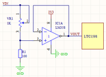
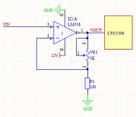
I need measure 16 channel 0-10V or 4-20mA.
I use LTC1598 with VCC = 3V3 and Vref = 2V5

Now, i want convert be 0-2V.
I have two ways to do this.
You can see in the attached file

But, i don't know a better way
What are good OPAMP ?

Thanks,
 

Attachments

  • 1.png
    1.png
    7.3 KB · Views: 160
  • 2.png
    2.png
    7.6 KB · Views: 153

Re: Convert 0-10V to 0-2V

Why not use only two resistors (potenciometer) as voltage divider?
 

Re: Convert 0-10V to 0-2V

Hi,

I do not know much about this
I see they have added a current buffer
can you explain for me when need it ?

Thanks,
 

Re: Convert 0-10V to 0-2V

But, i don't know a better way


Your first image is actually a resistive voltage divider followed by voltage follower, this technique is often preferred over the use of a simple resistive voltage divider when the output is feed to an ADC.

The reasoning is the added output impedance due to the resistive network of the voltage divider, the total resistance must be high enough to sufficiently limit current flow, while maintaining a low enough output impedance (source resistance) to prevent improper operation/transfer to the ADC stage.

The voltage follower overcomes these limitations by providing a very low output impedance (source resistance), even with a relatively high input impedance of a voltage divider.

Excess source resistance can serious impair the operation of an ADC, including the maximum sample rate and specified accuracy.

Recommend limits on source resistance largely depends on the ADC device and are usually addressed in its datasheet:

Reference: LTC1594/LTC1598 Datasheet, Section: Source Resistance, Page 16
Source Resistance

The analog inputs of the LTC1594/LTC1598 look like a
20pF capacitor (CIN) in series with a 500Ω resistor (RON)
and a 45Ω channel resistance as shown in Figure 8.
CIN gets switched between the selected “analog” and
“COM” inputs once during each conversion cycle. Large
external source resistors and capacitances will slow the
settling of the inputs. It is important that the overall RC
time constants be short enough to allow the analog
inputs to completely settle within the allowed time.

The datasheet also recommends a few Opamps for signal processing, like a voltage follower:

Reference: LTC1594/LTC1598 Datasheet, Section: Input OpAmps, Page 16
Input Op Amps

When driving the analog inputs with an op amp it is
important that the op amp settle within the allowed time
(see Figure 7). Again, the “analog” and “COM” input
sampling times can be extended as described above to
accommodate slower op amps. Most op amps, including
the LT®1006 and LT1413 single supply op amps, can be
made to settle well even with the minimum settling
windows of 4.8μs (“analog” input) which occur at the
maximum clock rate of 320kHz.

The following graph depicts the dramatic impact excessive source resistance has on the sampling times:

9_1345613774.jpg


BigDog
 
Re: Convert 0-10V to 0-2V

The right side circuit with the resistive network connected to the negative input of the opamp is an amplifier so I can't see how you intend to use it for attenuation, the min gain is 1.

I think a resistive divider would work fine, just add a capacitor across the ADC input so that the S&H circuit sees a low impedance instead of the higher resistance of the divider but this will have some effect on the speed of the input so if your signal is changing fast then it may be better to use the divider followed by the opamp buffer.

Alex
 

Hi all,

1,
Why not use only two resistors (potenciometer) as voltage divider?

Because i haven't precision resistor. I use a variable resistor to overcome this.

2, LTC1598LIG provide a built-in sample and hold function.
How to adaptation of impedance ?
I think just like the picture 1 in last attachment.

3, I have power supply 3V3. Can use it for LM358 ? ( Because i haven't LT1413 )
with input maximum = 2V

4, I designed into two parts
a, voltage conversion circuit
b, measure voltage used LTC1598LIG circuit ( schematic as datasheet ) :

I layout as shown:
Top layer :
TOP.png

Bottom layer :
BOTTOM.png

Part name:
PartName.png

I separate digital signal and analog signal.
Bottom layer as GND plane. It has two breaks due to signal traces.
Is it true ?

I use Sallen-Key antialiasing filter. But i don't know should G = ? and f = ? with sampling frequency = 100Hz


The firt, i design ADC circuit .
Thank for your help.
 

Status
Not open for further replies.

Part and Inventory Search

Welcome to EDABoard.com

Sponsor

Back
Top