Continue to Site

Welcome to EDAboard.com

Welcome to our site! EDAboard.com is an international Electronics Discussion Forum focused on EDA software, circuits, schematics, books, theory, papers, asic, pld, 8051, DSP, Network, RF, Analog Design, PCB, Service Manuals... and a whole lot more! To participate you need to register. Registration is free. Click here to register now.

Folded Dipole Antenna

Status
Not open for further replies.
ok..
for example, i'm using:
dielectric constant = 2.2
substrate's height = 1.575

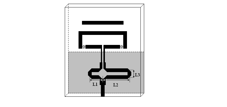
thus, how can I calculate the length of L1,L2 and L3?

for you information, symmetry that have been mentioned by me is L1 = L2 (refer new figure). is it possible to have situation like this?

 
Last edited:

Hi frankieNrosie.
From your figure, that you attached, you cannot have L1 = L2 for acheiving 180 phase difference.
 

Hi, I forgot to ask you. What is the frequency of operation ?
 

Download the transmission line calculator (TxLine)from AWR Corporation. It's free to download and a very useful calculator. Click the link below:


Using the TxLine calculator, you can calculate the lengths (L1 and L2) for yourself.

-sv
 

i dont understand how to use it. can u teach me about it?
 

if i'm not mistaken, that video shows how to determine the dimension of feeding line. am I right? currently, i want determine the dimension of balun.
 

Yes, the video shows how to determine the width, length of a transmission line, given that you know the height of the substrate, dielectric constant of the substrate, frequency of operation, impedance of the transmission line and the Electrical Length of the transmission line. There will not be any calculators for determining the dimensions of the balun itself.

For example, in your design the input is split into two equal parts using a T-junction power divider. If 50 ohms is the impedance of the feed line, then the impedance of the arms L1 and L2 should be equal to 100 ohms (2*Zo). And you want to achieve 180 phase difference between the outputs.

In the Tx Line calculator, give the following inputs:
er = 2.2, h =1.575mm
freq = 5.8 GHz, Impedance = 100 ohms. The above parameters will be constant.
One thing that you need to change is the electrical length.
For one case select the electrical length = 90 deg and for the other case electrical length = 270 deg.
(Phase difference of 180 deg is achieved: 270-90=180)
Or you can select 45 deg and 225 deg also.

It's upto you to decide.

Hope this clarified.

-sv

Hi sv1437,
this is a very useful peice of information, however how do I calculate L3 on this? howcome adding another L2 and L3 wouldn't have any effect on the phase shift?and Im doing a similar design bytheway.thnx
 

Status
Not open for further replies.

Part and Inventory Search

Welcome to EDABoard.com

Sponsor

Back
Top