goshantry
Newbie level 6
- Joined
- May 4, 2012
- Messages
- 14
- Helped
- 1
- Reputation
- 2
- Reaction score
- 1
- Trophy points
- 1,283
- Location
- Delhi, India
- Activity points
- 1,361
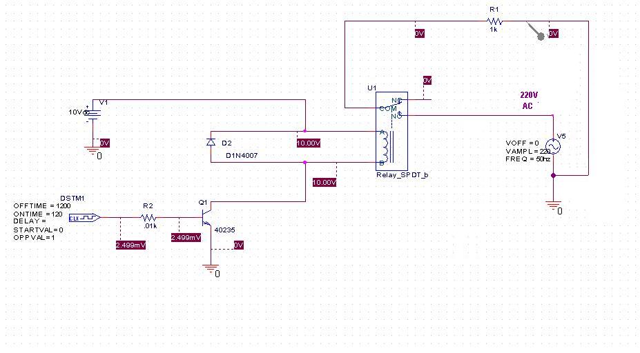
 i am trying to build a simple electronic switch with a transistor, relay and a microcontroller. i want to turn on the relay only when ethe microcontroller gives a high output. i am trying to simulate this circuit but cannot get the desired ac output.
please help me on this.
Last edited: