Continue to Site

Welcome to EDAboard.com

Welcome to our site! EDAboard.com is an international Electronics Discussion Forum focused on EDA software, circuits, schematics, books, theory, papers, asic, pld, 8051, DSP, Network, RF, Analog Design, PCB, Service Manuals... and a whole lot more! To participate you need to register. Registration is free. Click here to register now.

Driving two or more instrumentation amplifiers.

Status
Not open for further replies.

emsensors

Junior Member level 3
Joined
Jul 16, 2011
Messages
29
Helped
0
Reputation
0
Reaction score
0
Trophy points
1,281
Location
Iowa
Activity points
1,563
Hi,

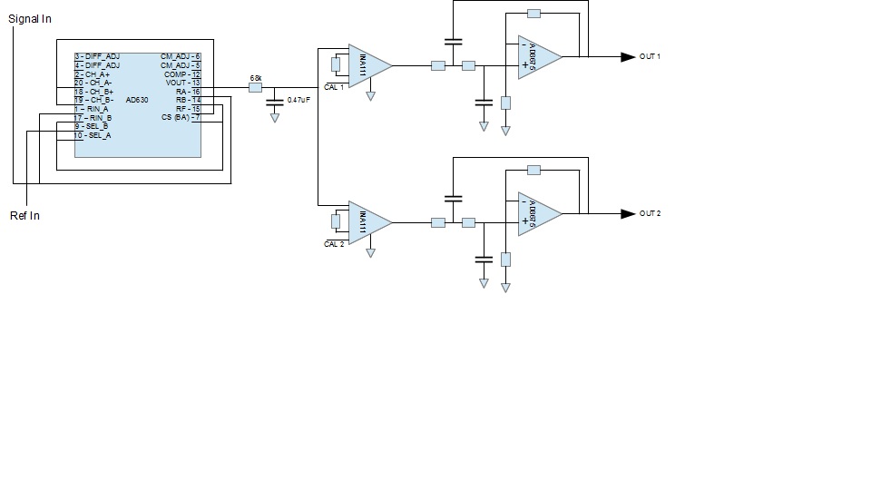
I am trying to get to the bottom of a rather stubborn circuit instability and want to rule out a few things. I am driving two instrumentation amplifiers (INA111's) - either both + inputs or both - inputs, never mixed - from a common source. The source is basically a passive low-pass filter. I figured that since the input impedance (of the instrumentation amplifiers) is very high then there should be no problems doing this. Am I right?

Thanks!
 

Sounds correct, but post your complete circuit so we can make a better analysis of the problem.
Do the amps have proper decoupling caps on the power pins?
 

Here is the circuit. Power supply pins are decoupled using a 4.7uF Tantalum in parallel with a 0.01uF ceramic capacitor. This is basically a detector circuit operating at 10 kHz. The two instrumentation amplifiers provide high- and low-sensitivity outputs. Thanks!

<a title="schematic_eda.jpg" href="http://obrazki.elektroda.pl/1717669700_1367190877.html"><img src="http://obrazki.elektroda.pl/1717669700_1367190877_thumb.jpg" alt="schematic_eda.jpg" /></a>

Sounds correct, but post your complete circuit so we can make a better analysis of the problem.
Do the amps have proper decoupling caps on the power pins?
 

What is the actual problem? Is the circuit oscillating, or what?

What are the opamps on the right? The markings look like AD667, but that's an AD converter, not an opamp.

Can you show values for the resistors and capacitors?


YOu are using a differential instrument Amp but as a single ended signal amplifier. WHo knows how much common mode or differential noise you have with reference signals that do not follow the same path as your signal. This could be your problem.
 

CAL1 and CAL2 are DC signals forming the second inputs to the two instrumentation amplifiers (INA111) so I think I am using them correctly, or am I missing something? Thanks.

YOu are using a differential instrument Amp but as a single ended signal amplifier. WHo knows how much common mode or differential noise you have with reference signals that do not follow the same path as your signal. This could be your problem.

- - - Updated - - -

The circuit oscillates VERY occasionally - for example, sometimes it is days before I see an oscillation. The oscillation builds and then dies - sometimes lasting a few seconds, sometimes a minute or so. I see the oscillation on data-acquisition system that samples at 500 msec. intervals so it is hard to say what frequency it is. It is so infrequent that I am never able to get a scope on the circuit to see what is really happening!

The Op-Amps are AD8675. The low-pass filter components are C=1uF, R=16k. The INA111 gain resistors are switched between 100Ohms and 50k so I have gain in the range 1 to 500.
 

Status
Not open for further replies.

Similar threads

Part and Inventory Search

Welcome to EDABoard.com

Sponsor

Back
Top