Continue to Site

Welcome to EDAboard.com

Welcome to our site! EDAboard.com is an international Electronics Discussion Forum focused on EDA software, circuits, schematics, books, theory, papers, asic, pld, 8051, DSP, Network, RF, Analog Design, PCB, Service Manuals... and a whole lot more! To participate you need to register. Registration is free. Click here to register now.

Diode Surge Ratings

Status
Not open for further replies.

ElecDesigner

Member level 5
Joined
Jul 22, 2014
Messages
94
Helped
4
Reputation
8
Reaction score
5
Trophy points
1,288
Activity points
2,190
I'm using diodes that will conduct very high currents for tens or hundreds of us a few times per second only so am looking at very short pulse capability.

Diodes such as this one.....
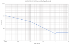
..give max I2t ratings for pulses above 10ms length and I2(root)t ratings for shorter than 10ms. The above 10ms rating is normally a 1/10th of the other rating which makes the 10ms numbers tie up.

My question is very simple... if only the above 10ms value is specified, do we assume the below 10ms value is 10 times that in all cases. See the attached graph.
 

Attachments

  • CaptureDiode.PNG
    CaptureDiode.PNG
    45.7 KB · Views: 107
Last edited:

Not really, on the chart you can see an inflection about 10ms
(where you roll from an adiabatic heating, to some fraction
having time to thermally-conduct out) and finally (with some
evidence of hand-waving) a steady state plateau.

Use the region appropriate to the stress, But if the question
is about applying this example, to a different part, then you
need to know thermal differences or take data.

A diode can be its own temp sensor if you want to take the
thermal data; a bilevel pulse, one to force power and one to
measure resulting Vf@If, which you'd also characterize as a
"cal map", and an idea of what junction temp corresponds
to their rating "cliff", and you can get your own pulse rating.
 
The discontinuity at 1 sec shows that a recent grad with no experience of power electronics took the measurements for this graph - and then did the graph ...
 
I'm probably missing the obvious, but I've found a formula that finds i2t from Itsm, that being ...... ((Itsm)^2)/200.
My answer then corresponds exactly to the VS-45EPS12LHM3 datasheet (as plotted in the graph above). but if I read off the graph I get 0.707 of the Itsm value. It's like there is a rms creeping in somewhere but I can't see how.

Your post #1 mentions root, namely 'I2(root)t'.

0.707 is an oddity because it's half the square root of 2 (1.414), and at the same time the reciprocal.

Square root of 200 is 14.14.
 
I have an application that has really high currents through diodes for say 100-200us a few times each second.
Diodes such as these.... https://www.vishay.com/docs/96475/vs-65eps16lhm3.pdf
.... specify surge ratings as non-repetitive.
Is there a generally accepted derating for repetitive capability or is it suffice to keep the junction temperature below max?

Is there a rule of thumb or anything about how surge ratings change with initial junction temperature?
 

work out the energy per pulse diss in the diode, then work out the rise in Tj per pulse assuming no heatsink then work out the highest Tj starting point such that the pulse will not cause Tj to exceed 150 deg C on the junction.

Knowing the average dissipation: energy per pulse diss in the diode x pulses per sec, then work out the heatsinking required to keep the Tj ave below the starting point arrived at above - this will give a little margin.

easy peasy
 
Status
Not open for further replies.

Similar threads

Part and Inventory Search

Welcome to EDABoard.com

Sponsor

Back
Top