Manolitus7
Newbie level 5
Hi everyone, I'm doing an electronics project, and I'm one step away from finishing it.
The situation in which my work finds itself is as follows:
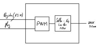
I have a set of digital data (Audio) of 16 Bits each sample, which are sampled at a certain frequency, with its corresponding flag between samples.
In order to convert that signal into audible, I need to do a PWM modulation, and filter it later.
I have searched for information about PWM modulation, where it talks about carrier and modulator signal, but I can't understand its purpose, I don't know if someone could explain to me what it consists of, and how it could be implemented in VHDL.
Thank you all.
M
The situation in which my work finds itself is as follows:
I have a set of digital data (Audio) of 16 Bits each sample, which are sampled at a certain frequency, with its corresponding flag between samples.
In order to convert that signal into audible, I need to do a PWM modulation, and filter it later.
I have searched for information about PWM modulation, where it talks about carrier and modulator signal, but I can't understand its purpose, I don't know if someone could explain to me what it consists of, and how it could be implemented in VHDL.
Thank you all.
M