Continue to Site

Welcome to EDAboard.com

Welcome to our site! EDAboard.com is an international Electronics Discussion Forum focused on EDA software, circuits, schematics, books, theory, papers, asic, pld, 8051, DSP, Network, RF, Analog Design, PCB, Service Manuals... and a whole lot more! To participate you need to register. Registration is free. Click here to register now.

connecting output to input in vhdl

Status
Not open for further replies.

rastor

Newbie level 6
Joined
Mar 28, 2010
Messages
11
Helped
0
Reputation
0
Reaction score
0
Trophy points
1,281
Location
canada
Activity points
1,355
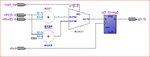
I have the following code:
Code:
LIBRARY ieee;
use ieee.std_logic_1164.all;
use ieee.std_logic_arith.all;
use ieee.std_logic_signed.all;

Entity count1s IS
	PORT ( 	oPC : in std_logic_vector(3 downto 0);
				offset: in std_logic_vector(3 downto 0);
				load_bta : in std_logic;
				q : out std_logic_vector(3 downto 0);
				clock : in std_logic );
end count1s;

architecture arch of count1s is
	SIGNAL c1 : std_logic_vector(3 downto 0);
	SIGNAL c2 : std_logic_vector(3 downto 0);
	begin
	process(clock)
	begin
		c1 <= oPC + "0001";
		c2 <= oPC + offset;
		
		if (clock'event and clock='1') then
			
			if (load_bta='1') then
				q<=c1;
			else
				q<=c2;
			end if;
		end if;

	end process;

end arch;

my question is how can i connect q to one of the input of the bottom adder. i tried
Code:
oPC <= q;
but no luck. Any idea/suggestions? I have attached the output image of the above code.
Thank you.
 

Attachments

  • Capture.JPG
    Capture.JPG
    75.3 KB · Views: 518

good question i will also tried that in verilog hdl. which software you use for that. i think you use the quartus software it easy to do that in this software.
i think it is better to you.
good luck.
 

yes i am using quartus 10.0

---------- Post added at 05:32 ---------- Previous post was at 05:31 ----------

actually it should be
Code:
q <= oPC
, and from what i understand it should be outside the process. correct me if i am wrong.
 

The question isn't clear at all.
What do you want?
oPC <= q;
or
q <= oPC;
And where do you want to connect it.

In both cases you have to keep the VHDL syntax rules:
- a signal can only have one driver, except inside a process, where multiple drivers are allowed (and the last wins).
- a port output signal can't be read inside the entity unless you change it to buffer

As an additional remark. If you prefer to learn VHDL by trial-and-error method, which isn't probably that bad, please read the compiler error messages thoroughly, particularly the first one (the others may be follow-ups). It usually tells exactly what you did wrong.
 

I agree with FvM what you want to do is not clear.

q<=oPc has no interest. it will just create a wire.
If you want to connect output to the input either you do it when you instantiate your module either you remove oPc and connect an internal signal from output to input of your adder, which is not the input of your module.
In both case I suggest you to add a reset to your flip-flop

Regards
 

Sorry guys if i wasn't clear. I want a line going from q to oPC.you guys can see the attached image.

thanks.
 

with your code it is not possible.
IF you want to do this inside your module.

You must change oPc from Input to signal and use an intermediate signal before q like :

signal q_int;
process
...
q_int<=c1;
...
end process;
...
oPc<=q_int;
q<=q_int;
As FvM said you can not have several driver for a signal because you will have a contention.

If you want to keep oPc as input. The only way I see is to do this outside the module you instantiate it.

Regards
 
Last edited:
  • Like
Reactions: rastor

    rastor

    Points: 2
    Helpful Answer Positive Rating
thank you, jducluzeau. it actually worked.
 

There is an alternative to declare q as a buffer or using an intermediate signal:

oPC <= q'driving_value;

This will work even if port q is if type "out", but I don't have enough experience to tell if it is good or bad coding practice.
According to my book, this attribute was introduced in VHDL-93.
 

It may be valid VHDL, but I would consider it bad practice, its better to generally stay away from signal attributes when it comes to synthesis.
Nowadays, even using a buffer isnt exactly standard practice.

Normally, its recommended you use an internal signal and read that instead of the port.
 

I agree, stay away from attributes (I had bad experience with it porting my code from one vendor to another.

Buffer is an option, but more and more it's being replaced with a temp signal.
 

Status
Not open for further replies.

Similar threads

Part and Inventory Search

Welcome to EDABoard.com

Sponsor

Back
Top