Continue to Site

Welcome to EDAboard.com

Welcome to our site! EDAboard.com is an international Electronics Discussion Forum focused on EDA software, circuits, schematics, books, theory, papers, asic, pld, 8051, DSP, Network, RF, Analog Design, PCB, Service Manuals... and a whole lot more! To participate you need to register. Registration is free. Click here to register now.

[SOLVED] Circuit design to test capacitor.

Status
Not open for further replies.

ShuKosugi

Junior Member level 1
Joined
Nov 22, 2013
Messages
19
Helped
1
Reputation
2
Reaction score
1
Trophy points
3
Activity points
148
Hello...really appreciate someone can share me a circuit design that can electrically test and detect faulty capacitor (beside ESR meter or any capacitor meter).
Using function generator and oscilloscope can be fine...thanks
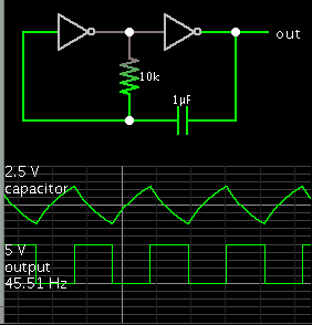
 

I like this oscillator circuit because the capacitor's characteristics are the chief factor, and they are easy to observe.

6901227600_1459178462.png


- - - Updated - - -

Hmmm... Now I notice the capacitor has a negative charge for half the cycle. This may not be good for electrolytics.
 

Thanks to both of you BradtheRad. Thanks also Kripton2035, I will find time to explore your link. I would like circuit design that can test also polarized capacitors...Am still open for any suggestions...thanks.
 

If you have an oscilloscope, Brad's oscillator is a pretty simple method for mid range non polarised capacitor values.

Something like a 555 timer will work better with very large polarised electrolytics.

For much smaller values you can use your function generator with a known reference inductor to find the resonant frequency by exiting it with your function generator.

Very different methods are needed for testing say 100pF, 1uF or 10,000uF.
 

Status
Not open for further replies.

Part and Inventory Search

Welcome to EDABoard.com

Sponsor

Back
Top