Continue to Site

Welcome to EDAboard.com

Welcome to our site! EDAboard.com is an international Electronics Discussion Forum focused on EDA software, circuits, schematics, books, theory, papers, asic, pld, 8051, DSP, Network, RF, Analog Design, PCB, Service Manuals... and a whole lot more! To participate you need to register. Registration is free. Click here to register now.

Change a front of clock signal

Status
Not open for further replies.

ustinoff

Member level 2
Joined
Mar 6, 2016
Messages
45
Helped
4
Reputation
8
Reaction score
4
Trophy points
8
Location
Russia
Activity points
308
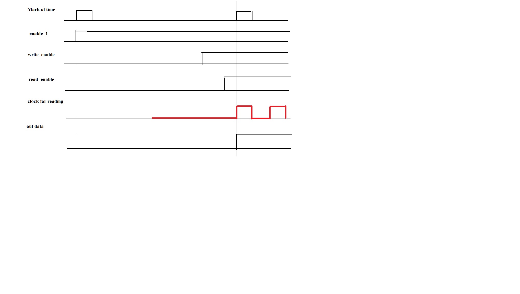
Hello. I do not understand, how i can do next thing.

I want to get "clock_out" with the same frequancy that "slow_clock", but
if "enable" changing from '0' to '1' or after 1-3 times of "fast_clock"
my next blocks must feel changing from low front to high front (rising_edge(clk) in terms of VHDL).

I tried to do it with next code:
Code:
process(enb,fast_clock,slow_clock)
begin
  if rising_edge(fast_clock) then
    if enb='1' then
      if slow_clock='1' then
        clock_out <= slow_clock;
      elsif slow_clock='0' then
        clk_out <= not(slow_clock);
      end if;
    else
      clk_out <= '0';
    end if;
  end if;
  end process;
 

Using clock as data and generate clocks as in your example is likely to cause timing problems. It would be helpful if you specify the problem completely, e.g. with a timing diagram.
 

Using clock as data and generate clocks as in your example is likely to cause timing problems. It would be helpful if you specify the problem completely, e.g. with a timing diagram.

I need to send 2 signal in synch with mark of time.

I have 2 independent data streams, and i must start to send both synch with special mark of time. The mark has 100 ns high front and 1 second has low front; and it's periodic signal.

Freq.-s of both signals is non-constant.
I try to do next thing: when the first high front of mark come i make "enable" signal. After changing the "enable" signal starts to work some blocks, and both of streams i'm writing in RAM (not at all 1 second long,of course). When next mark coming i make "enable" for reading from RAM and in start post's i wrote my attempt to generate clock for reading.
 

Timing diagram here.

/Mark of time/: 100 ns high front and 1 second has low front signal;

enable_1 - blocks start to work from this signal;

write_enable - enable to write RAM;

read_enable - enable to read RAM;

clock for reading - (red color) this signal i want to use for reading
from RAM and it i tried in the first post.

And finally, out data - one (for simplify) data stream what i have.


You don't show the relationship between your clocks described in the first post and this timing diagram.
 

You don't show the relationship between your clocks described in the first post and this timing diagram.

In my code from the first post i tried to get red signal from timing diagram. The red signal must has the same freq. like slow clock.
 

The "code" in post #1 is unable to generate the red clock signal. There is no logic that sets the clock signal high and low again without an respective input.

A timing diagram should show the fast clock timing too, or indicate somehow if it can be considered much faster than the other input signals.

You'll probably need internal state signals (a finite state machine) to generate the intended out clock sequence. You'll also need provisions to synchronize the logic input to the fast clock in case the could change during a clock edge.
 

First, let me say that you should look at your FPGA of choice and read the clocking resources guide. You should be using these primitives to solve the problem, unless you are only creating a simulation model.

clock switching/gating has a few failure modes that need to be addressed. The solutions tend to require hardware support. Further, routing clocks through internal logic has many additional problems. For clocking, it is much better to use the dedicated resources than try to emulate them in general purpose resources.

That said, you might also consider resyncronizing signals from a faster, free running clock. It isn't clear if this is a viable option or not.
 

Status
Not open for further replies.

Similar threads

Part and Inventory Search

Welcome to EDABoard.com

Sponsor

Back
Top