Welcome to our site! EDAboard.com is an international Electronics Discussion Forum focused on EDA software, circuits, schematics, books, theory, papers, asic, pld, 8051, DSP, Network, RF, Analog Design, PCB, Service Manuals... and a whole lot more! To participate you need to register. Registration is free. Click here to register now.
thank you very much keith...
can i ask another question?
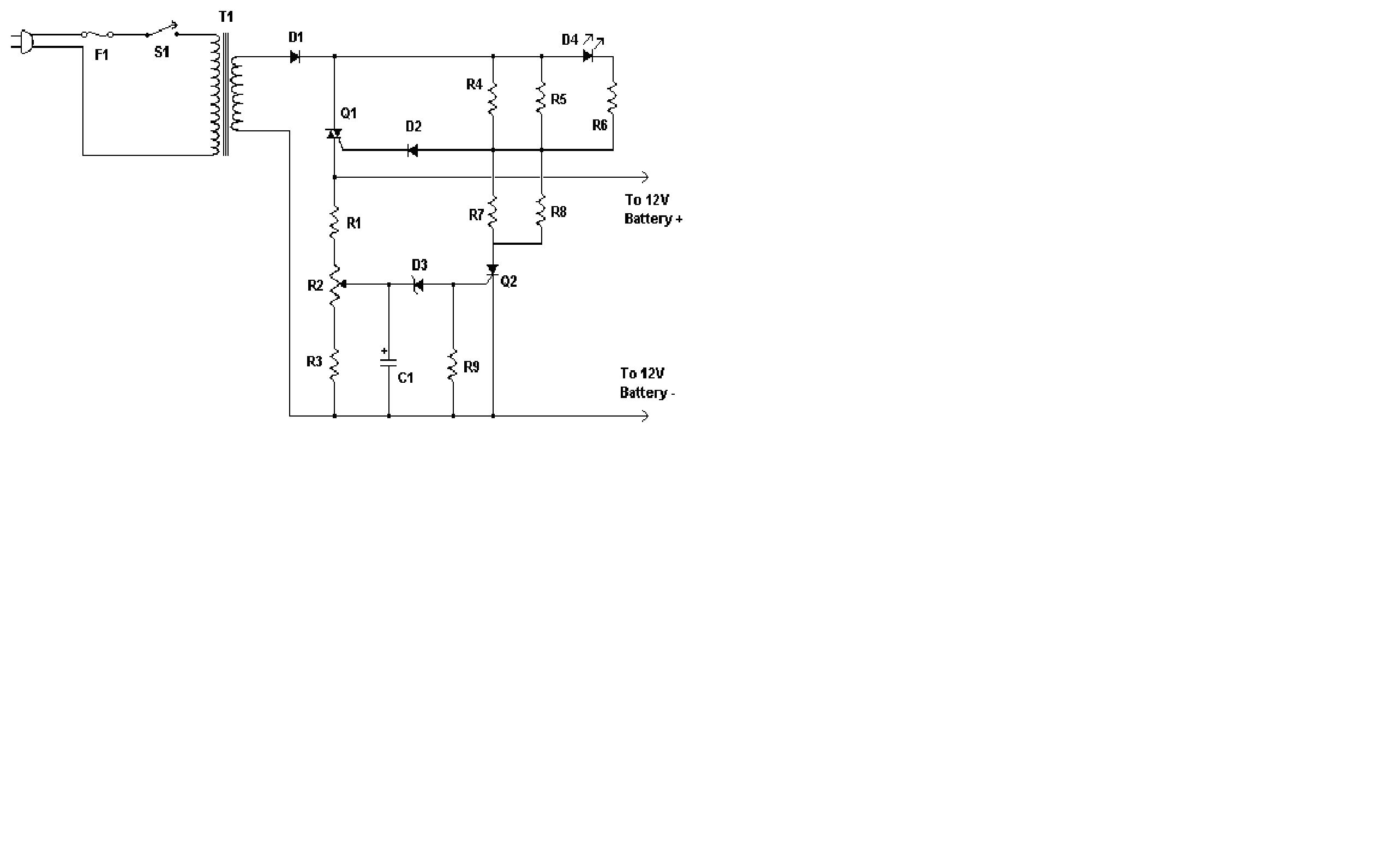
I would like to attach this lead acid battery charger to an inverter ive shown before to ensure that anytime there is a drop in the battery voltage, it will automatically recharged. Do think it is possible?
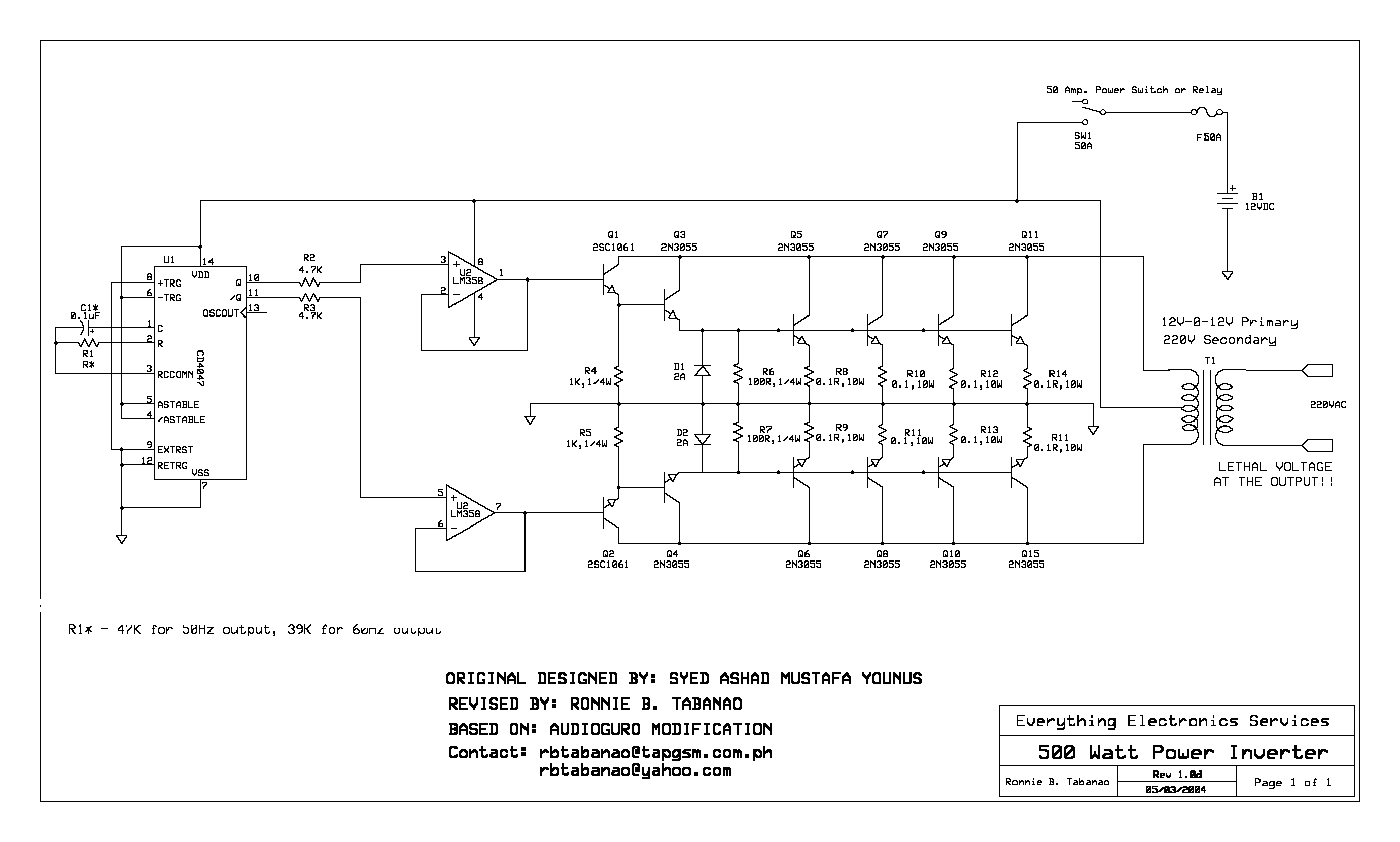
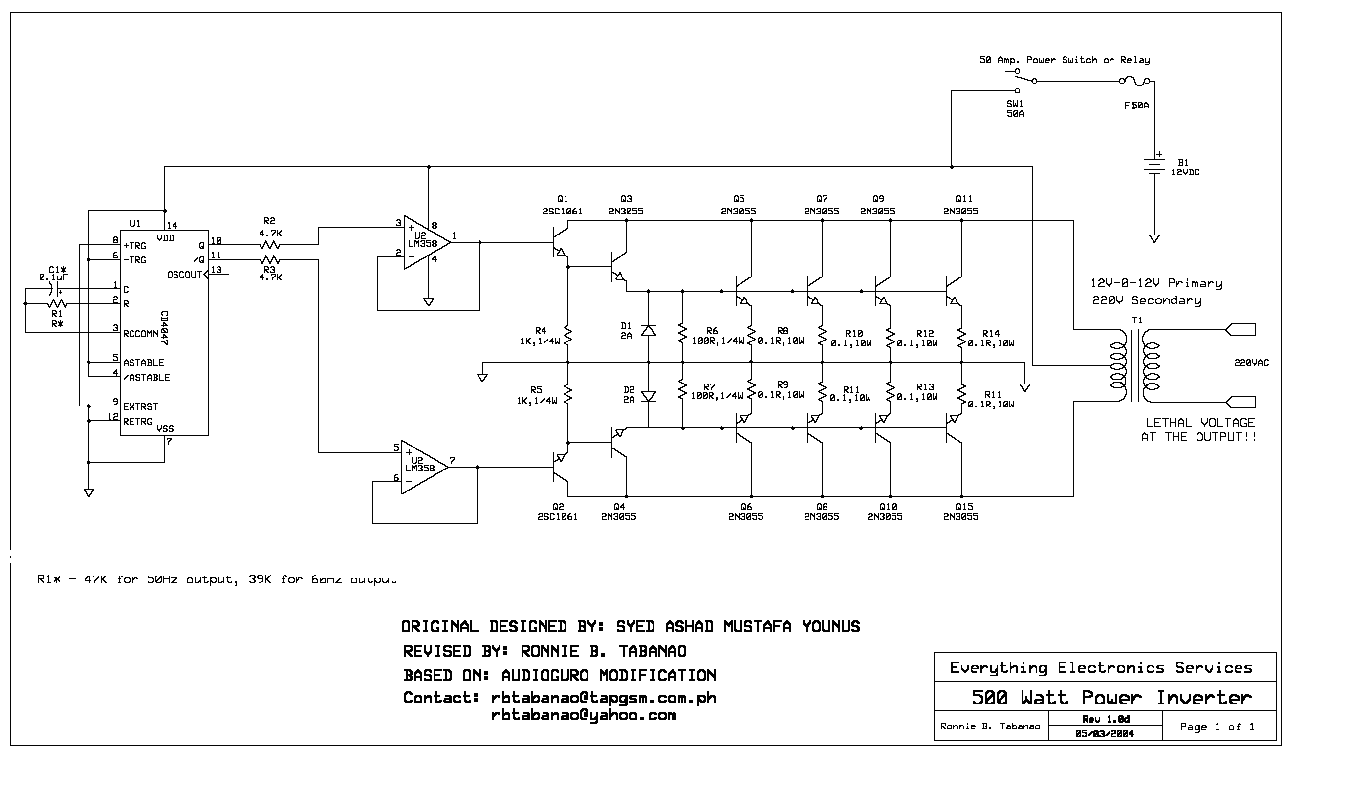
i build this inverter i used 10A step up transformer but the output is only mV i also checked my connection. can somebody help me to trouble shoot this circuit? these is very important for me to finish this project...
This site uses cookies to help personalise content, tailor your experience and to keep you logged in if you register.
By continuing to use this site, you are consenting to our use of cookies.