Continue to Site

Welcome to EDAboard.com

Welcome to our site! EDAboard.com is an international Electronics Discussion Forum focused on EDA software, circuits, schematics, books, theory, papers, asic, pld, 8051, DSP, Network, RF, Analog Design, PCB, Service Manuals... and a whole lot more! To participate you need to register. Registration is free. Click here to register now.

Hoby project: looking for help validating part selection and finding DC-DC booster

cyrilleB

Newbie
Joined
Oct 9, 2023
Messages
4
Helped
0
Reputation
0
Reaction score
0
Trophy points
1
Activity points
86
Hello,

I have an engineering background, but I am not a EE. Which is why I am seeking help here.

I am designing a small PCB to carry an arduino and include 2 stepper drivers (DRV8825) and one DC-DC, 5V to 12V voltage converter (<10W).

I have done the base design/pcb (visible at: https://oshwlab.com/cyrille.de.brebisson/melt )
But I still need some help identifying/verifying the component selection for the resistor/capacitor (footprint and other details which elude me).

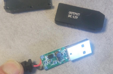
I am also looking for help/advice to add a 5V to 12V DC-DC convertor to generate 12V from the USB vbus for the 2 steppers (small, 0.3A@3.6V/phase)

Thanks for any help you can bring!
Cyrille
 
Why do you need 12V if your steppers run off of 3.6?

Regardless, you're up against the laws of physics. You need 0.3A x 2motors x 2(?) phases from your 12V supply. That's 14.4 Watts. Most USB ports supply 0.5A at 5V. That's 2.5W. USB 3.0 is better, with 0.9A, but that's still only 4.5W. You're going to somehow have to create energy out of thin air. There are other higher power USB ports, make sure you're using one of those.
 
Hi,

First: desiging an SMPS is not an easy task. You should be able to understand
* current loops (current flow)
* loop inductance
* GND planes
* HF behaviour

Part selection:
* either use what you are familiar with
or
* go to a SMPS_IC manufacturer of your choice internet site,
* look for the SMPS_IC selection tool,
* give your requirements,
* read some of the datasheets of the recommended ICs (briefly)
* choose an IC
* read the datasheet thoroughly
* look for application notes, example designs, design tools
* follow the guidelines. They tell you all you need to know to make the circuit work.

Klaus
 
Hello

>Why do you need 12V if your steppers run off of 3.6?
The 0.3A/@3.6V per phase (*4) is the info needed to know the power requirement (4.32W).
However, the steppers are driven by a drv8825 which requires >=9V input voltage and which will generate the 3.6V.

I want to integrate the boost converter on my PCB so as not to have to rely on "modules" on top of my PCB (evertan 12V or the like)

I know that such convertors can be very small and "simple" because I regullary use cables like this:
- https://fr.aliexpress.com/item/1005004971876668.html
which (connected to a USB charger) will happily deliver around 15W of power...

The PCB is less than 1.5*1.5cm, 1 UC, 1 self, 3 resistors and 3 caps... Nothing "complex", but I can not read the markings, I do not know what the IC is, what the refs are for the parts, and I know that component placement and grounding the like is critical, I know that I am out of my depth...

If someone could point me to a project on easyeda (or similar) that I could copy and paste, I probably could do it...

Thanks,
Cyrille
 

Attachments

  • dcdc.png
    dcdc.png
    396.3 KB · Views: 41
The DRV8825 does NOT ”generate 3.6V”. It generates a PWM signal with an amplitude of 12V. It will control the average CURRENT into the phases. If the average current per phase is 0.3 A, you need 0.3 x 12 watts/ phase, or 14.4 W per motor, not 4.32W.
 
The DRV8825 does NOT ”generate 3.6V”. It generates a PWM signal with an amplitude of 12V. It will control the average CURRENT into the phases. If the average current per phase is 0.3 A, you need 0.3 x 12 watts/ phase, or 14.4 W per motor, not 4.32W.

When the driver input is 12V ... and one phase current is PWM´d to be 0.3A avg,
then the (non rotating) motor draws 0.3A (average) at 3.6V (average) which means 0.3A x 3.6V = 1.08W
Now let´s assume the PWM controller works with 80% efficiency, then the input power (to the driver) is 1.08W/0.8 = 1.35W
The difference 0f 0.27W is dissipated as heat.

1.35W input power on 12V means a current of 1.35W / 12V = 0.115A.
So far for "stand still" and only one coil powered.
***

There are different driving schemes that may power two coils .. maybe only part of the time.
We don´t know this. Thus it´s impossible to calculate ...

***
When the motor rotates .. it obvioulsy generates rotating power/energy.
This needs to be input as P = V x I.
The current is regulated by the controller to be 0.3A.
But now - because the motor rotates - the average coil voltage is not 3.6V anymore, it becomes higher.
In worst case the PWM is 100% at 0.3A, the voltge across the coil obviously then is a bit below 12V.

So for this worst case situation the power supply current is 0.3A @ 12V per driven coil.
We don´t know neither RPM nor torque requirement, theu unable to calculate...

***

It´s quite usual that stepper motors like this (0.3A, 3.6V) are controlled by 12V, 15V, 24V, 36V ... or even higher.
The benefit is that the motor then can provide (almost) full torque at higher RPM.

Klaus
 
I'm not sure that's true. Why is
a PWM stepper controller is a current control loop designed as step down using the motor´s inductance.

It´s far from a linear regulator regarding power conversion and dissipation.

Klaus
 
a PWM stepper controller is a current control loop designed as step down using the motor´s inductance.

It´s far from a linear regulator regarding power conversion and dissipation.

Klaus
Ah, I wasn’t figuring the inductance. I was figuring if the average current in the motor is 0.5A, the current from the supply is also 0.5A. I wasn’t considering any energy-storage element.

And my previous post wasn’t finished before it got erroneously posted, and then i got distracted :)
 
This is what I used for my CNC and is what I recommend you choose.

Arduino Nano with GRBL ucode https://github.com/gnea/grbl/wiki
CNC Shield with adjustable current limit
12V supply for Arduino with 5V LDO and 12V to Shield.
GRBLPanel for Windows and USB to Nano. https://github.com/gerritv/Grbl-Panel/releases

Use buffered step 10us
Set max acceleration according to max inertial load. With no load 1 meter seeks in <1s.
Set max velocity to anything that works.
Set mechanical home switches at preferred datum corner.
Use full steps for hi-torque and fractional steps for slow quiet operation.
Use good cable strain reliefs, z-fold or ribbon loop for gantry.
Use PE ground for low EMI.

Using UBS boost to 12V motor drivers is not recommended with surge currents, back EMF and SMPS EMI data interference issues possible.
 
Last edited:
Hello,

Although I understand the rationale around the power discussion, the problem is that it does not seem to match reality.

In another project, I have been using this cable: https://fr.aliexpress.com/item/1005004971876668.html to power an arduino nano and 2 "classic" nema17 at 1.5A@3.06V per phase (so around 18W in theory), and, measuring the power on the 5V USB end of this 5 to 12V cable, I see a power consumption of around 2.5A or 12.5W!

Don't ask me why or how (maybe I never actually use the full power on the motors, not needing full torque?)! But I know for sure that It works!


Anyhow, this project uses 2 0.3A@3.6V per phase motors (it is a MUCH smaller device), so, since my other, much more power intensive project works, then I am relatively certain that this less demanding project would also work with the same "architecture"...
BTW: here are the motors that I am using here: https://www.arrow.com/en/products/14hk0402-117n/moons-industries

This other project I talked about, using a separate USB cable for data and USB to 12V "convertor" means 2 cables where one would be enough.

This is why I am trying to integrate the DC-DC convertor from the cable to the PCB.

To answer the questions on torque and RPM.

The top speed will be around 6 RPM (10s to a turn) with around 300g, mounted on bearings, to move for motor one and less than 20g for motor 2.

Here is my current 3D model for the project. It is a mini telescope, 3D printed. The diameter of the coupola is 13cm.
Motor one will turn the coupola, motor 2 will only turn the camera (OV2640 module with a 50mm focale lens).
So minimal torque/speed requirements.

Cyrille
 

Attachments

  • coupola.png
    coupola.png
    149.9 KB · Views: 34
Hi,
the problem is that it does not seem to match reality.
I´m quite sure it does. ... if you consider the real conditions.

****
2 "classic" nema17 at 1.5A@3.06V per phase (so around 18W in theory),
1.5A @ 3.06V = 4.59W
But when you say 18W, this means you calculate with 2 Motors and both windings of the motor fully powered.
This simply is not the case in reality.

The motors have the specifications... but you are responsible to adjust the driver to meet the motor´s requirements.
Did you properly adjust the current to be 1.5A max at the coils?

****
Your 5V --> 12V cable.
You say 2.5A and 12.5W. This means you calculate with 5V. So 2.5A at the 5V side. The USB 1.0/2.0 and the connectors are not designed for 2.5A.
They are designed for 0.5A.
So I´d say this clearly is against the standards. If you say it works this way ... then please don´t be surprised if something sometimes go up in flames.

I personally recommend to investigate the true power requirements and use a proper 12V supply.
****

You show the datasheet.
I´ve worked with stepper motors. The datasheets of my stepper motors provide a lot more informations about RPM, torque vs RPM .... and driving modes ... and so on.
You get what you pay for. Cheap motors --> low quality, low reliability, less informations.

****
6 RPM is at the lower end of RPM. So you don´t need to worry about rising coil voltage.

****
300g of mass. Is not very important. It´s the inertia that counts.
And not every 300g cause the same inertia.
For example: The diameter counts. Inertia of 300g of a long, thin rod is low, whereas inertia of 300g wide wide disc is much higher.

Klaus
 
Hello,

>1.5A @ 3.06V = 4.59W But when you say 18W, this means you calculate with 2 Motors and both windings of the motor fully powered.
>This simply is not the case in reality.
> The motors have the specifications... but you are responsible to adjust the driver to meet the motor´s requirements.
> Did you properly adjust the current to be 1.5A max at the coils?

Well, I adjusted the trim potentiometer on the DRV to 0.75V, which, according to the official documentation for the carrier board that I use on that project, means 1.5A per coil.
I did not put an ampmeter on the phase to check. But the system dlivers suficent torque there to move my 3KG telescope with 3KG of counterweight around 20cm away from the center of rotation.

****
>Your 5V --> 12V cable.
>You say 2.5A and 12.5W. This means you calculate with 5V. So 2.5A at the 5V side. The USB 1.0/2.0 and the connectors are not designed for 2.5A.
>They are designed for 0.5A.
>So I´d say this clearly is against the standards. If you say it works this way ... then please don´t be surprised if something sometimes go up in flames.
0.5A on USBA is USB 2.0 standard for data connections (USB3 is 0.9 I think)
But USB A connectors have been, for a long time, able to send WAY more power than that for charging...
I have one of these inline USB power meters and I have measured my external battery happily delivering 2A. My charging plugs delivering over 4A!
My computer will happily send 1.5A before it complains about a "powerr surge" and cuts the USB port.
This charger, for example, advertises 3.1A on USB A: https://www.amazon.fr/Chargeur-Multiport-Compatible-téléphone-Tablette/dp/B0C2336R7J

>I personally recommend to investigate the true power requirements and use a proper 12V supply.
This morning I used my other 2 motor project and replaced the motors there by the ones that I want to use for this project, and I measured 0.7A@5V on my 5-12V USB convertor cable...
However, my newer project, using an ESP32 will use slightly more power than the arduino Nano...

****
>You show the datasheet.
>I´ve worked with stepper motors. The datasheets of my stepper motors provide a lot more informations about RPM, torque vs RPM .... and driving modes ... and so on.
>You get what you pay for. Cheap motors --> low quality, low reliability, less informations.
Yep, I fully agree with you here... Getting proper information is next to impossible unless you are a professional with a contract with the manufacturer and stuff like that.
For individual hobyist... you are SOL! It is frustrating as it breaks a lot of the open source principle because, althrough you have source code (or example schematics), you still can't really do anything because of walled off documentation...

****
>300g of mass. Is not very important. It´s the inertia that counts.
>And not every 300g cause the same inertia.
>For example: The diameter counts. Inertia of 300g of a long, thin rod is low, whereas inertia of 300g wide wide disc is much higher.

Yep. In my case, the 3D print of the coupola and deck is 160g. relatively uniformaly spread with a maximum radius of 6.5cm.
The rest of the mass (2*60g motors + PCB + camera=30g) is in the center (within 4cm of the center), so not contributing much to the inertia...
So, I am not too concerned seeing that my other project (the one with the nema17) moves over 7kg of mass spread much furter...

Cyrille
 
Getting proper information is next to impossible unless you are a professional with a contract with the manufacturer and stuff like that.
I don´t agree.
The manufacturers are interested in selling these products. Thus they support you with informations for you to make it easy and reliable.
I only once in my decades of professinal career to sign an NDA for an extremely new and advanced product.

Any other device´s datashet I found in the internet. But I´m focussed on high quality products. Yout experience with buying the cheapes parts on the market may differ.

Klaus
 
The reality is each coil is 12 Ohms or 1A if supplied per coil from 12V.
Why boost to 12 when the coils are better suited with a buck regulator to 3.6 or PWM to 72% max from 5V? (1.08W/coil x 4 = 3.32W)
Std USB ports are 12W.
This is what you need to provide with a power supply, and a 12V boost is not required unless you wanted to exceed power with acceleration then hold at 3.6V.
 
Getting proper information is next to impossible unless you are a professional with a contract with the manufacturer and stuff like that.

Its complicated. Service is proportional to opportunity size in quite a few organizations brain pan.
On more than one occasion I was advised not to spend time serving certain small accounts, but
did so anyways, on the sly. As a Field Application Engineer. In other cases my bandwidth so
limited I had no choice to not service.

On semiconductors, I always used several paths to get info, FAE, Manufacturers Representative, direct calls
to factory asking for product engineer, Regional Sales Manager offices, even design engineer on some occasions.
Persistence often of value. My experience most engineers want to take care of customers. Most, not all.

As far as sales, even their motivations sometimes diverted because of crazy baseless beliefs, interpretations,
and conclusions. Humans after all probably the most flawed living creatures on the planet........


Regards, Dana.
 
OKAY, Do you have enough understanding yet to go ahead without 12V?

Coil L = 8 mH, R = 12 Ohms
Response time Tau= L/R = 8m/12 = 0.67 ms
Thus step response time at 1kHz max rate, & if torque greatly exceeds load, using 3.6V or 5V at 72% max. PWM will work..

BTW this response assume bipolar FET drivers with low Rdson.
DRV8825 = 0.32 Ω at 24V, 1A @ 85'C
 
Last edited:

LaTeX Commands Quick-Menu:

Part and Inventory Search

Welcome to EDABoard.com

Sponsor

Back
Top