T
treez
Guest
Hello,
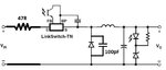
We are using a 1W , LNK302 based High voltage buck converter in our offline 230VAC, 150W linear LED driver which uses linear mode led drivers (they successively switch in/out banks of leds to keep efficiency high). The 1W Buck supplies the bias power for the LED current controllers.
So, to summarise, the only SMPS on the 150W PCB is the 1W Buck converter.
From scoping, we know that the Buck converter is operating in Burst mode, and when it is switching, it is in continuous mode.
We recently changed the Buck diode from a US1J (trr=75ns) , to a STTH1R06A (trr = 25ns).
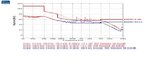
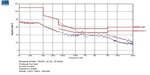
However, since this change, the conducted EMC scan has gotten worse as the attached shows.
Do you think this worsening could have been caused by the faster Buck diode?
The only other changes made were that we are now using a 220nF ceramic capacitor downstream of the mains rectifier bridge, whereas before we were using a 220nF X2 capacitor upstream of the mains rectifier bridge. Also, the other change is that we now have no “quiet node” copper under the switching node of the Buck converter, whereas before we did….so I suppose in the previous PCB there might have been better shielding of the switching node from the earthed heatsink on which the whole PCB sits.
STTH1R06A datasheet:
https://www.st.com/content/ccc/reso...df/jcr:content/translations/en.CD00005135.pdf
US1J diode datasheet:
https://www.vishay.com/docs/88768/us1.pdf
LNK302 datasheet:
https://www.mouser.com/ds/2/328/lnk302_304-306-179954.pdf
We are using a 1W , LNK302 based High voltage buck converter in our offline 230VAC, 150W linear LED driver which uses linear mode led drivers (they successively switch in/out banks of leds to keep efficiency high). The 1W Buck supplies the bias power for the LED current controllers.
So, to summarise, the only SMPS on the 150W PCB is the 1W Buck converter.
From scoping, we know that the Buck converter is operating in Burst mode, and when it is switching, it is in continuous mode.
We recently changed the Buck diode from a US1J (trr=75ns) , to a STTH1R06A (trr = 25ns).
However, since this change, the conducted EMC scan has gotten worse as the attached shows.
Do you think this worsening could have been caused by the faster Buck diode?
The only other changes made were that we are now using a 220nF ceramic capacitor downstream of the mains rectifier bridge, whereas before we were using a 220nF X2 capacitor upstream of the mains rectifier bridge. Also, the other change is that we now have no “quiet node” copper under the switching node of the Buck converter, whereas before we did….so I suppose in the previous PCB there might have been better shielding of the switching node from the earthed heatsink on which the whole PCB sits.
STTH1R06A datasheet:
https://www.st.com/content/ccc/reso...df/jcr:content/translations/en.CD00005135.pdf
US1J diode datasheet:
https://www.vishay.com/docs/88768/us1.pdf
LNK302 datasheet:
https://www.mouser.com/ds/2/328/lnk302_304-306-179954.pdf