Continue to Site

Welcome to EDAboard.com

Welcome to our site! EDAboard.com is an international Electronics Discussion Forum focused on EDA software, circuits, schematics, books, theory, papers, asic, pld, 8051, DSP, Network, RF, Analog Design, PCB, Service Manuals... and a whole lot more! To participate you need to register. Registration is free. Click here to register now.

Buck converter EMC fail must be common mode problem?

cupoftea

Advanced Member level 5
Joined
Jun 13, 2021
Messages
2,612
Helped
54
Reputation
108
Reaction score
115
Trophy points
63
Activity points
13,700
Hi,
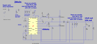
We are doing a Buck with Vin=24-32V, VOUT=13V5 AND iOUT = 15A at 450kHz.

From the LTspice simulation attached, it shows that the tiny input filter of just three 10uF,50V MLCCs and one 1uH inductor has pretty much filtered out all of the switching ripple!
Supposing this converter then failed conducted EMC, then do you agree that the problem must be common mode, because the diff mode filtration simply has filtered
out pretty much all of the diff mode disturbance?

If this converter failed conducted EMC, would you be sure that it was a common mode problem?

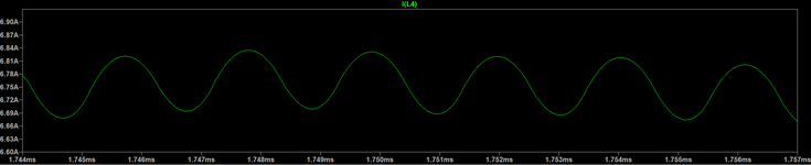
The close up waveform of the input current shows a smooth 450kHz sinewave of some 120mApkpk....such a waveform is far too smooth to fail
any EMC test?
 

Attachments

  • Buck EMC problem.png
    Buck EMC problem.png
    64.6 KB · Views: 39
  • Input current before and after EMC filter.png
    Input current before and after EMC filter.png
    12.7 KB · Views: 35
  • Close up of input current waveform1.png
    Close up of input current waveform1.png
    19.6 KB · Views: 31
Last edited:
I wouldn't agree with the assumption its common mode, it could easily be differential, Your simulation is just that. In the real world you have parasitic elements, layout considerations, component noise, harmonic elements and bandwidth limitations to name but a a few which mean it could still be differerential.

Also not sure what spec your testing to but 120mA ripple sounds pretty big for an EMI type frequency.
 
DC SMPS are not subject to conducted emissions, (only AC inputs) so DC-DC boards are more a concern for radiated emissions. Your differential filter “could” be conducting too much sine current, if you do not have a good Balun, otherwise OK. Spread spectrum would be better with the same noise current, if that were possible.

Your ground plane will become a patch antenna of all the current spectrum in Vin to Gnd unless perfectly RF balanced cancelling emissions, far-field, occur from the power plane.
 
Last edited:
Under FCC statute ( USA ) and EU statutes ( and many other countries standards regimes ) - any device that is an unintentional radiator is subject to EMI limits and more especially if it interferes with legitimate comms - whereupon it can be ordered to stop by the FCC ( and fined if they so wish )

So it is generally a good idea to see if any device you design or cause to have made - is reasonably quiet

Having said that - you refer to LT-spice sim of a filter - have you put in the R & C for the chokes ? and the R and L for the caps ?

in the real world ( IRL ) these parasitics ( and pcb layout ) generally give you different filtering than you expect, with peaks and dips in the attenuation curve

using a cheap VNA to spot this is a good idea
 
This question is a non sequitur fallacy, as the suggested conclusion does not follow the assumption.

Although DCDC converters are the risk of failing EMI with an ACDC adapter, there is no reason that a sine wave is low in level just because it has no harmonics.

1713407551258.png
 
Thanks, generally speaking, with good layout and reasonable filtering, for the above spec, what would you expect the typical ratio of common mode to diff mode
noise to be. Bearing its mind its a non isolated Buck.
 
Again conducted only applies to AC units and the Balun filters out a lot (30 dB) of CM over 2 decades.

Better designs have 2 Baluns of different cores to span over 4 decades of RF with “good” attenuation. This is a result of the core to Y caps impedance ratio before self resonance (STF) . But is for the AC interface.
 
CM emissions ( conducted ) are affected by capacitance to earth - because the currents / voltages in the 2 lines are common to earth - hence the term.

Modelling this in Spice is really a waste of time - as physical elements tend to dominate - for example above 450kHz the length of the attached wires determines how effective a radiator the system is - and therefore whether there would be a tendency to exceed radiated limits.

We have to meet RFI/EMC standards for the DC lines on telecom power supplies - we never model this - testing is the only way.

Obviously a lot of CM currents in the DC lines above 450kHz requires us to test for radiated in a typical system setup.
 
DC SMPS are not subject to conducted emissions, (only AC inputs) so DC-DC boards are more a concern for radiated emissions. Your differential filter “could” be conducting too much sine current, if you do not have a good Balun, otherwise OK. Spread spectrum would be better with the same noise current, if that were possible.

Your ground plane will become a patch antenna of all the current spectrum in Vin to Gnd unless perfectly RF balanced cancelling emissions, far-field, occur from the power plane.
"DC SMPS are not subject to conducted emissions"

I find that an interesting comment, could you elaborate please? I do Aircraft parts and both DC and AC systems have to to meet both conducted and radiated emissions.
 
"DC SMPS are not subject to conducted emissions"

I find that an interesting comment, could you elaborate please? I do Aircraft parts and both DC and AC systems have to to meet both conducted and radiated emissions.
I was neglecting specialized industries which ignore IEC, FCC, EU regulations have their own rules like Telco, Aero, Space, Nuclear etc. User in those fields don't cross paths here much although I was in all of these at different stages of my career.
I welcome your insights.
 
We have to meet RFI/EMC standards for the DC lines on telecom power supplies - we never model this - testing is the only way.
Thanks, see your point, i used to work with an engineer who designed SMPS for the UK military....they said that finding the values and amounts of ferrite beads, y caps and common mode chokes needed to pass common mode EMC was a bit like, "throwing currents into a cake"
 
I was neglecting specialized industries which ignore IEC, FCC, EU regulations have their own rules like Telco, Aero, Space, Nuclear etc. User in those fields don't cross paths here much although I was in all of these at different stages of my career.
I welcome your insights.
Thank you, I was generally curious. I've been 22 years in the Aerospace sector so my experience is very specific to that. I was intrigued but the statement because it is often the greatest headache :)
 
Agency approvals have their boundaries, when it comes to legal authority.

When we did the world's 1st ISDN Broadband WAN with DS1 to 100 homes in 1979, I was amazed our customer MTS did not care about FCC and supplied their own power from central office batteries. That was until I used a Canadian Tire charger as a backup to the subscriber terminal motherboard in the basements modified with an LED and DC power switch. We had to get a Provincial waver for $50 because it was illegal to use a modified UL/cUL approved equipment on customer premise. (LOL). (Although we invented our own emission and susceptibility tests for good measure with oscillating relay coils on antenna and spectrum analyzers for emissions.)
 

LaTeX Commands Quick-Menu:

Similar threads

Part and Inventory Search

Welcome to EDABoard.com

Sponsor

Back
Top