Continue to Site

Welcome to EDAboard.com

Welcome to our site! EDAboard.com is an international Electronics Discussion Forum focused on EDA software, circuits, schematics, books, theory, papers, asic, pld, 8051, DSP, Network, RF, Analog Design, PCB, Service Manuals... and a whole lot more! To participate you need to register. Registration is free. Click here to register now.

buck converter floating error

Status
Not open for further replies.

khaled ragab

Junior Member level 1
Joined
Feb 15, 2012
Messages
19
Helped
0
Reputation
0
Reaction score
0
Trophy points
1,281
Activity points
1,442
edaboard.png

i'am trying to implement buck converter where the input volt is 15v and the output volt is 3v and the output current is 3A inductance is 2.2 mh capacitor is 100 uf mosfet is p channel irf9530 pwm is an amplified signal out of micro

the problem is as i connect the circuit the output voltage is equal to the input voltage (measuring it from the source pin also) it act as the source pin is floating
 

Dear khaled
Hi
Here is an IC , that can help you as well as , that you can find it in 3.3 volt and 5 volt and 12 volt and adjustable type ( buck regulator ) that named LM2576 . so i think it will be compact and good for 3 amperes . and for more currents you can use a simple optocoupler and mosfet after it .
Best Wishes
Goldsmith

---------- Post added at 03:12 ---------- Previous post was at 03:11 ----------

by the way , when you want design a switch mode regulator , you should give the command pulses , across the GS junction of your mosfet . that picture is just a functional block and not practical.
 

i correct the circuit but nothing happen,

i'am using an adapter of 0.5A as an input to the circuit does it effect?
 

Tell that how with 0.5A input current , you want achieve 3 amperes from that simple circuit ?????!!!!!!!!!
Regards
Goldsmith
 
Tell that how with 0.5A input current , you want achieve 3 amperes from that simple circuit ?????!!!!!!!!!
Regards
Goldsmith
i know that could be a problem but could this make the output voltage equal to the input volt

the voltage on the source pin is equal to the input volt(15v), as floating mosfet
 

can you attach the circuit that you are using ?

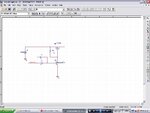
edaboard2.png

this is the circuit what i'am sure about is the micro+lm324 circuit as i designed it many times and i checked the mosfet to found if it works or not and it's fine, under the same condition i tried to connect a simple led and resistance and it works, all i do is removing the led circuit and connect the buck one it give me that output
 

It is completely wrong!
your driving has , problem . you should reflect 15 volt just across the GS junction.
Good luck
Goldsmith
 

It is completely wrong!
your driving has , problem . you should reflect 15 volt just across the GS junction.
Good luck
Goldsmith
i didn't get it what to reflect on the gs(gate source!) junction
 

well ! if you simply , give some volts to the gate at this arrangement , it will be at linear region , and it means that , your mosfet at high currents , will convert to the HELL !!!!!!! ( high value of dissipation ).
so you should follow , this circuit :
PFET.JPG
Best Lucks
Goldsmith
 

well ! if you simply , give some volts to the gate at this arrangement , it will be at linear region , and it means that , your mosfet at high currents , will convert to the HELL !!!!!!! ( high value of dissipation ).
so you should follow , this circuit :
View attachment 69246
Best Lucks
Goldsmith

and the command is out of the micro directly, the q1 transistor could be bc547b or not
 

it respond with the same values, could the problem be the current because the mosfet act as it is floating(not connected) because i have tried the schematic that i upload several times and it works, does the input current has to do with any thing while designing buck converter?
 

there is a note when i remove the capacitor from the schematic the voltage across the load(resistance) is equal to the desired output due to duty cycle problem solved but when i connect the capacitor again the voltage jump to 15 volt(input voltage) and the voltage across the capacitor does not vary with the pwm
 

The circuit with the LM324 doesn't work because the output of the LM324 cannot reach the positive rail so the PMOS can never turn off. It might have worked if the opamp was rail to rail output.

Keith
 
The circuit with the LM324 doesn't work because the output of the LM324 cannot reach the positive rail so the PMOS can never turn off. It might have worked if the opamp was rail to rail output.

Keith
how to fix this?
but when i remove the capacitor the circuit works fine, when i put it back the voltage jump to the input volt

---------- Post added at 11:42 ---------- Previous post was at 11:32 ----------

Resold all components near Capacitor and check its Function again.
i'am checking the implementation first on a breadboard
 

Status
Not open for further replies.

Similar threads

Part and Inventory Search

Welcome to EDABoard.com

Sponsor

Back
Top