wandola
Junior Member level 3
Dear all,
I am designing a low-to-medium S/H circuit for an ADC. The sampling switch is a bootstrapped switch to linearize the on-resistance.
I first designed a bootstrapped switch, and I simulated the waveforms and obtained DFT and THD in cadence with the calculator.
After that, I also designed a dummy switch to cancel the charge-injection and clock feedthrough. I think the results is not bad.
I also obtained the new output DFT and THD. However, I found the DFT plot of the S/H output with and without dummy is almost the same. ( the 2nd harmonic, 3rd harmonic, magnituedes are almost the same)
But from the transient simulation results I can see the S/H with dummy actually has betteer accuracy.
Can anyone command on this?
You can see the three lines for Vin, Vout_no_dummy and Vout_withdummy, respectively.
I am designing a low-to-medium S/H circuit for an ADC. The sampling switch is a bootstrapped switch to linearize the on-resistance.
I first designed a bootstrapped switch, and I simulated the waveforms and obtained DFT and THD in cadence with the calculator.
After that, I also designed a dummy switch to cancel the charge-injection and clock feedthrough. I think the results is not bad.
I also obtained the new output DFT and THD. However, I found the DFT plot of the S/H output with and without dummy is almost the same. ( the 2nd harmonic, 3rd harmonic, magnituedes are almost the same)
But from the transient simulation results I can see the S/H with dummy actually has betteer accuracy.
Can anyone command on this?
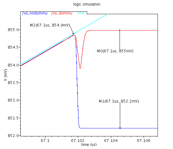
You can see the three lines for Vin, Vout_no_dummy and Vout_withdummy, respectively.

