Continue to Site

Welcome to EDAboard.com

Welcome to our site! EDAboard.com is an international Electronics Discussion Forum focused on EDA software, circuits, schematics, books, theory, papers, asic, pld, 8051, DSP, Network, RF, Analog Design, PCB, Service Manuals... and a whole lot more! To participate you need to register. Registration is free. Click here to register now.

Battery voltage on ADC

Status
Not open for further replies.

HighTechPower

Member level 5
Joined
Jul 10, 2020
Messages
91
Helped
0
Reputation
0
Reaction score
0
Trophy points
6
Activity points
703
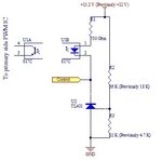
Hi. I recently made 1.5 A charger for 12 V, 7 Ah lead acid batteries. I'm reading battery voltage using microcontroller ADC with resistor divider network. ADC reads while battery is charging and red LED is blinking. When it is charged it should activate a buzzer (depending on whether buzzer activation switch is on or not) and green LED should light up. Sometime it reads correct value and some time it shows amazingly battery as charged even when it is in charging phase and voltage is much lower when measured using multimeter. Any idea how to fix this issue? This circuit converts any 12 V switching power supply into 1.5 A battery charger circuit while raising it's voltage to 15.2 V (after diode D3 I get 14.8 V max). Then control pin is connected directly to optocoupler LED's cathode pin which controls the power supply feedback.

Please attached here find the schematic and code.

C:
 // PIC12F683 Configuration Bit Settings

// 'C' source line config statements

// CONFIG
#pragma config FOSC = INTOSCIO  // Oscillator Selection bits (INTOSCIO oscillator: I/O function on RA4/OSC2/CLKOUT pin, I/O function on RA5/OSC1/CLKIN)
#pragma config WDTE = OFF       // Watchdog Timer Enable bit (WDT disabled)
#pragma config PWRTE = OFF      // Power-up Timer Enable bit (PWRT disabled)
#pragma config MCLRE = OFF      // MCLR Pin Function Select bit (MCLR pin function is digital input, MCLR internally tied to VDD)
#pragma config CP = OFF         // Code Protection bit (Program memory code protection is disabled)
#pragma config CPD = OFF        // Data Code Protection bit (Data memory code protection is disabled)
#pragma config BOREN = OFF      // Brown Out Detect (BOR disabled)
#pragma config IESO = OFF       // Internal External Switchover bit (Internal External Switchover mode is disabled)
#pragma config FCMEN = OFF      // Fail-Safe Clock Monitor Enabled bit (Fail-Safe Clock Monitor is disabled)

// #pragma config statements should precede project file includes.
// Use project enums instead of #define for ON and OFF.

#include <xc.h>

#define _XTAL_FREQ 4000000

void init_micro (void);
void init_timer (void);
void init_adc (void);
void read_adc(void);

static int adc = 0, toggle_flag = 1, timer_flag = 0, adc_flag = 0;
static int counter_a = 0;

#define LED_CHARGING GP4    //RED LED
#define LED_CHARGED GP5        //GREEN LED
#define BUZZER GP2            //BUZZER
#define TRUE 1
#define FALSE 0
#define PB_SWITCH GP3        //BUZZER ON/OFF SWITCH
#define POWER_GOOD GP0        //ACTIVATES THE RESISTOR DIVIDER

void main (void)
{
    init_micro();
    init_adc();
    init_timer();
    do
    {
        if(adc_flag)
        {
            read_adc();
              if(adc < 820)            //BATTERY NOT FULL
            toggle_flag = TRUE;
            else if(adc >= 820)        //BATTERY FULL
            toggle_flag = FALSE;
            adc_flag = FALSE;
        }                 
        if(timer_flag)
        {
            counter_a++;
            timer_flag = FALSE;
        }
        if(counter_a >= 10)
        {
            counter_a = 0;
            if(toggle_flag)
            {
                LED_CHARGING ^= 1;
                LED_CHARGED = 0;
                BUZZER = 0;
            }
            else if(!toggle_flag)
            {
                LED_CHARGING = 0;
                LED_CHARGED = 1;
                if(PB_SWITCH)
                BUZZER ^= 1;
                else if(!PB_SWITCH)
                BUZZER = 0;
            }
        }
    }
    while(TRUE);
}

void init_micro (void)
{
    OSCCON = 0b01100111;
    TRISIO = 0b00001010;
    CMCON0 = CMCON0 | 0b00000100;
    ANSEL = 0b01010010;
    GPIO = 0b00000000;
    POWER_GOOD = TRUE;
    __delay_ms(100);
}

void interrupt team_isr()
{
    if(TMR1IF)
    {
        TMR1H = 0xCF;
        TMR1L = 0x2C;
        timer_flag = TRUE;
        TMR1IF = 0;
    }
  
    if(ADIF)
    {
        adc_flag = TRUE;
        ADIF = 0;
        GO_nDONE = 1;
    }
}

void init_timer (void)
{
    T1CON = 0b00110100;
    TMR1H = 0xCF;
    TMR1L = 0x2C;
    TMR1IE = 1;
    PEIE = 1;
    GIE = 1;
    TMR1ON = 1;
    TMR1IF = 0;
}

void init_adc (void)
{
    ADCON0 = 0b10000100;
    ADON = 1;
    ADIF = 0;
    ADIE = 1;
    PEIE = 1;
    GIE = 1;
    GO_nDONE = 1;
}

void read_adc (void)
{
    adc = (((unsigned)ADRESH << 8) | ADRESL);
}

Green LED normally lights up at 14.48 V (even then is not it too early as compared to 820 ADC value. Also note I have limitation that battery voltage does not rise above 14.5 V though it's new battery that is why I by trial and error chosen 820 for 14.48 V).
 

Attachments

  • Charger Front.PDF
    362.7 KB · Views: 129
Last edited:

This is a fundamentally flawed design. There are some software issues with the ADC but what does it measure if you disconnect the battery? Does it still say it is charged if the battery is removed?

Brian.
 

This is a fundamentally flawed design. There are some software issues with the ADC but what does it measure if you disconnect the battery? Does it still say it is charged if the battery is removed?

Brian.

Yes Brian. If battery is removed it says battery is charged and green LED lights up as it should according to schematic.
 

Hi,

We already discussed about this circuit.
Did you follow the recommendations.

Code:
It's not well documented.
I can't find out ADC sampling rate, whether sampling rate and data processing is synchronized, or whether the variable needs to be "volatile", or you need atomic variable access.
I see no digital filter, no plausibility check.

In the schematic I miss the complete charging circuit, don't know whether charging current is smooth or pulsed.
Don't see the wiring to detect possible GND bounce.

Hard to give good assistance.

Klaus
 

Hi,

Did you follow the recommendations.

Klaus

This time I did not put coding inside ISR and I think that's good.

Hi,

Code:
It's not well documented.
I can't find out ADC sampling rate, whether sampling rate and data processing is synchronized, or whether the variable needs to be "volatile", or you need atomic variable access.

Klaus

I want to know more about this if I have missed something in coding.

Hi,

In the schematic I miss the complete charging circuit, don't know whether charging current is smooth or pulsed.
Don't see the wiring to detect possible GND bounce.

Hard to give good assistance.

Klaus

I checked on scope and its shows smooth DC voltage level.
 

Sim of power switch and processor monitor V point -

1615726424828.png


Regards, Dana.
 
Last edited:

Sim of power switch and processor monitor V point -

**broken link removed**


Regards, Dana.

Hi Dana. I get around 2.61+ voltage at divider when +VBATT is around 14.46 V.
 

Yes Brian. If battery is removed it says battery is charged and green LED lights up as it should according to schematic.
Maybe I'm not understanding, your first post suggests you have built a charger and this is for monitoring the voltage of a battery connected to it. Nothing wrong with that, but if it says the battery is full when it has been disconnected it either means the monitor is attached to the battery, not the charger, or that it can't working properly. Ignoring the fact that terminal voltage is not a good representation of charge level, the charging voltage has to be higher than battery voltage for the charger to work, so disconnecting the battery will leave more than 12V across the charging points and therefore say it is fully charged when it isn't actually there at all.

A better strategy is to measure the voltage using at least three trigger points, charging, charged and disconnected. Using a single point will work but risks the alarm intermittently triggering as the threshold is met and failure to detect a missing or open circuit battery.

Ideally, you would monitor charging current as well because even a heavily discharged battery may still measure full voltage while accepting charge and you would use hysteresis by using an upper and lower alarm/LED threshold to avoid false triggering when 'on the brink' of operating. Even better would be to alternate charging and applying a load while measuring the voltage as this gives a far better representation of charge state. You can still do all this in your PIC12F683.

In the software, as well as using different thresholds there should only be one place where the ADC conversion is started and one place you enable interrupts, you have two of each!

Brian.
 

Hi Dana. I get around 2.61+ voltage at divider when +VBATT is around 14.46 V.

Should not it be exactly 2.5 V at that level.
--- Updated ---

In the software, as well as using different thresholds there should only be one place where the ADC conversion is started and one place you enable interrupts, you have two of each!

Brian.

Sorry I could not got your point?
--- Updated ---

Ideally, you would monitor charging current as well because even a heavily discharged battery may still measure full voltage while accepting charge and you would use hysteresis by using an upper and lower alarm/LED threshold to avoid false triggering when 'on the brink' of operating. Even better would be to alternate charging and applying a load while measuring the voltage as this gives a far better representation of charge state. You can still do all this in your PIC12F683.

Brian.

As you pointed, may be by independently measuring battery voltage while applying some dummy load while disconnecting charger circuit part may produce stable ADC value.
 
Last edited:


I used 1% resistors for voltage divider.
--- Updated ---

Hi,

In the schematic I miss the complete charging circuit, don't know whether charging current is smooth or pulsed.
Don't see the wiring to detect possible GND bounce.

Hard to give good assistance.

Klaus

I simply changed the two resistors values around TL431 in switching power supply and thus raised voltage from 12 V to 15.2 V to be supplied to monitoring circuit. Please note in schematic where there is written +12 V assume it as +15.2 V instead.
 
Last edited:

I used 1% resistors for voltage divider.

So we would have 2% error (one leg of divider high, the other low) + measurement error, external
and internal, the processor A/D and external voltmeter, excluding any noise effects.

In sim, the DC Op Point, I get 2.501V for 14.46 Vbatt, exact resistor values.


Regards, Dana.
 

So we would have 2% error (one leg of divider high, the other low) + measurement error, external
and internal, the processor A/D and external voltmeter, excluding any noise effects.

In sim, the DC Op Point, I get 2.501V for 14.46 Vbatt, exact resistor values.


Regards, Dana.

But I'm getting 2.61+ voltage and that's a big difference. From circuit it's not clear why it's behaving so.

I just changed the multimeter but its still reading 2.61+ V at voltage divider instead of 2.5 V.

While stuffing board I using multimeter carefully double checked that resistors of voltage divider are of same values as mentioned in schematic.
 
Last edited:

Whats the drop across drain to source on PMOSFET ?

Drop on processor gnd pin to supply ground ?

Using scope on infinite persistence look at A/D pin and Vdd pin on processor
to get an idea of total pk-pk noise. Keep probe gnd short, set to x 10.


Regards, Dana.
 
Hi,
I simply changed the two resistors values around TL431 in switching power supply
I see no TL431 in the given schematic..

I just changed the multimeter but its still reading 2.61+ V at voltage divider instead of 2.5 V.
Possible reasons:
* wrong DVM measurement
* Ground bounce
* pullup current on PIC pin

Klaus
 
Hi,

I see no TL431 in the given schematic..


Possible reasons:
* wrong DVM measurement
* Ground bounce
* pullup current on PIC pin

Klaus

You even don't see the switching power supply as that is on the backend.

I want to know more about last reason you pointed out as pullup current on PIC pin?
 

Hi,

Does it make sense to mention a part that is on a foreign circuit?

Pullup: all professionals need to read datasheets.
So if I need to know details about this I had to read about port setup.

I still don't see what the charging concept is. Usually for lead acid one uses CC / CV charging method. A usual power supply is not meant to work on CC mode. It may have some protection features, maybe resulting in hickup mode, but no current regulation...

But without the missing informations mentioned in post#4 .... I can not be much of help here...

Klaus
 

Hi,

I still don't see what the charging concept is. Usually for lead acid one uses CC / CV charging method. A usual power supply is not meant to work on CC mode. It may have some protection features, maybe resulting in hickup mode, but no current regulation...

But without the missing informations mentioned in post#4 .... I can not be much of help here...

Klaus

Hi Klaus. Please note that this schematic is meant to create CC feature by circuitry built around 0.47 Ohm, 2 W resistor. Other than that I simply raised power supply voltage to 15.2 V and after diode D3 I get around 14.8 V in CV mode.
 

Hi,

A series resistor does not result in CC mode, nor CV mode.
Either poor design or you hide informations about how you achieve CC operation.

We don't know how exactly you come to the measurement values. Maybe you measured
* the voltage across the battery (which is not the same as the voltage divider voltage .... because of R10, wiring resistance...)
* and the voltage across R13

I don't want to annoy you with repeatedly asking for informations. We are in post#19, so I guess you have your reasons.

Good luck
Klaus

Hi Klaus. Please attached here find the schematic (on power supply side) to explain how I control the switching power supply in CC & CV mode using single opto-coupler IC.
--- Updated ---

Hi,

Possible reasons:
* wrong DVM measurement
* Ground bounce
* pullup current on PIC pin

Klaus

I removed the PIC IC from socket and by manually enabling resistor divider I still see 2.61 V.
 

Attachments

  • Control.jpg
    Control.jpg
    41.2 KB · Views: 105
Last edited:

Status
Not open for further replies.

Similar threads

Part and Inventory Search

Welcome to EDABoard.com

Sponsor

Back
Top