Continue to Site

Welcome to EDAboard.com

Welcome to our site! EDAboard.com is an international Electronics Discussion Forum focused on EDA software, circuits, schematics, books, theory, papers, asic, pld, 8051, DSP, Network, RF, Analog Design, PCB, Service Manuals... and a whole lot more! To participate you need to register. Registration is free. Click here to register now.

Audio Amplifier. Which class should I use?

Status
Not open for further replies.
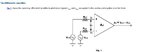
To design a power amplifier, all we are really trying to do is to make an opamp that can deliver high output currents so that we can use a circuit like the one below.

The very easy way to do that is to start with a normal opamp, and add an output buffer to give the extra output current needed. As you say, opamps like the TL074 are limited to supplies of +-18V, but there are opamps that work with higher voltage supplies.

If we do that, then there isn't much to learn though. It would be better to design our own high power opamp using discrete transistors. This can be made up from the three gain stages I explained earlier.

Before we get into those details, there are some important considerations even in the simplified circuit below.

Firstly, there are the obvious points:
  • R1 sets the input impedance to 22K.
  • The ratio of R2 and R3 set the gain to 23, so a little less than 1V RMS input will give full power.
  • The combination of R1 and C1 roll off the low frequency response at about 8Hz.
  • The combination of R2 and C2 roll off the low frequency response again but at a much lower frequency, about 0.8Hz.
You can change any of those values as you choose, but there are some other considerations too:

A) Electrolytic capacitors are nasty.
They have lots of problems but the most important for audio circuits is that they create distortion. We want to have low distortion, so it is best not to pass the audio signal through electrolytic capacitors unless we really have to. Plastic capacitors e.g. polyester/mylar or polypropylene are much better.

C1 is only 1uF so there is no problem - we can use a plastic capacitor, but if we make the value of C1 too much higher, we will need a very large and expensive plastic capacitor, or an electrolytic. This also means we can't make R1 too small, because then C1 would need to be bigger.

C2 is a problem. The value has to be high (at least about 22uF), so we have to use an electrolytic. The answer here is to make the value much higher, say 220uF. This high value means that the signal voltage across the capacitor will be very small, so the distortion it causes will be very low.

B) DC offset.

We do not want any DC voltage across the loudspeaker. If we use a perfect opamp, then the capacitors in the circuit below would make sure there is never any DC voltage across the speaker, even if there is DC at the amplifier input. However opamps are not perfect (even ones we design ourselves).

The problem is that in our circuit, the inputs will be connected to the bases of the transistors in the first gain stage, and they will draw a small current. These currents flow through R1 and R3, causing a small voltage drop across them. If the voltage across those two resistors is the same, then they will cancel and there should be no DC voltage across the speaker.

There are four things we can do to make the voltages as close as possible:
  • Make the currents as small as possible by running the input transistors at a low collector current and choosing transistors with high current gain.
  • Make the currents as similar as possible by running both input transistors at the same collector current and using transistors with similar current gain.
  • Make R1 and R3 the same value.
  • Keep the value of R2 and R3 as small as possible.

So in summary, there are four guidelines:
  • Make R1 and R3 the same value.
  • If their value is too low, there will be a problem with the capacitors.
  • If their value is too high, there will be a problem with DC offset.
  • Make C2 a very high value to avoid distortion.


@goldsmith

It will be my pleasure that you expert teach me. I don't no how to thank you. I have no words.

Related to post:
I wanna ask that you said to achieve 50W I would need at least +-30V. Is it fixed voltage in order to design 50W amplifier?
 

Hi ahayaan
Don't forget that for complementary with simultaneous supply we will have this formula : Pout =Vcc^2/2*RL hence we can say : 30^2/2*8 -------> Pout max = 56 watts with neglecting some parameters .
Best Wishes
Goldsmith
 
Yes, I have calculated 56W too. But thought that we are actually designing for 50W. Now it is clear.
 

So , now what is your problem exactly ?
BTW : are you able to use a simulator to simulate your circuits before building ?
 

I want to say one most important thing here to everyone who is helping me especially goldsmith and godfreyl that as both of you are experienced electronics engineer no doubt, may *** bless you, but you must be known by the fact that number of minds is proportional to the number of the circuit design of the same project. Can you get what I am trying to say? I mean as both of you are trying to teach me designing audio amplifier. But logics are different as both of your experienced and minds are different. I hope you can understand me.

So kindly become one and try to teach me in a single way. If goldsmith gives another circuits to draw and godfreyl gives another then my mind will blow up, whom to be followed.

I hope you can understand.

Sorry for such bad English.

thanks.

---------- Post added at 02:28 ---------- Previous post was at 02:27 ----------

Yes I know how to use simulators.

Which one will you prefer me?

---------- Post added at 02:50 ---------- Previous post was at 02:28 ----------

My exact problem is anyone of you teach me. Because I can't follow both of you strategies separately for one project.

I prefer goldsmith you to teach me. However, godfreyl is also helping me but as I am newbie so he is not considering this and make me to follow him as a person who has already some practical experience. While on the other hand I need even smaller calculation.

Thanks. I will be very great full to both of you experts.
 

hello Shayaan,
may I help you please?

What you have to do is, You have to make a high speed,high power opamp.
Make a non inverting amplifier with that opamp.
Next, you have to make sure that at any temperature there is no DC offeset at output (means output voltage must be at half of supply voltage at all condition)
Next, make sure that the amplifier only amplifies audio range of the signal.

TDA2030 is like a high speed high power(14W) op amp. So at first you can make an amplifier with that. If you are succesfull, Then the only job will be make a more powerfull opamp like that. When you will see the datasheet of the TDA2030 you will find how to null DC offset, You will find how to eliminate very low frequency and very high frequency, so that only audio range gets amplified.

You may ask goldsmith to help you developing TDA2030 amplifier.
 
Last edited:

Hi again
See below , please :
Computer amp.JPG
Can you analyze this circuit ? if yes we can continue simply , but if not , i have to explain it .
Best Wishes
Goldsmith
 
Last edited:
Because I can't follow both of you strategies separately for one project.

I prefer goldsmith you to teach me.
Yes, I understand. It is better to follow just one path. I hope Goldsmith will guide you well. Good luck with your design.
 

@godfreyl

Thanks. But keep reviewing thread.

@goldsmith

Yes I can somehow.

At U1A Vin is at non-inverting but the output of U1A provides at the differential input U2A. Also U1A has negative feedback. U2A seems like inverting low pass filter. Right?
goldsmith can you comment what ahsan_eda says. I don't no how to use TDA2030. Is it pre-made audio amplifier? Comment please.

Thanks.

---------- Post added at 01:23 ---------- Previous post was at 01:11 ----------

@godfreyl

Thanks. But keep reviewing thread.

@goldsmith

Yes I can somehow.

At U1A Vin is at non-inverting but the output of U1A provides at the differential input U2A. Also U1A has negative feedback. U2A seems like inverting low pass filter. Right?
goldsmith can you comment what ahsan_eda says. I don't no how to use TDA2030. Is it pre-made audio amplifier? Comment please.

Thanks.
 

Hi again
The Ic that he introduced is a power amplifier , but not high power . for more detail you can refer to it's datasheet simply .
See below , please :
**broken link removed**
Click on datasheet download .
It has a simultaneous supply around +-18 volts . and you can use it as a preamplifier for your 400 W amp ! .
And it will be a good experience if you build it .
Anywhere :
U1 is non inverting buffer , right . ( just a simple buffer ) and R6 is a simple potentiometer to control the amplitude of voice .
Notice it will be a reasonable way to control the amplitude of voice before amplification . but if you want use microphone you should use a simple preamplifier to increase SNR ( signal to noise ratio ) . and C2 is prepared to eliminate the noises . and U2A is a simple inverting amplifier with Gain of Av= -ZF/R1 . so R1 is your input impedance . and the ZF is R2 in parallel
With C1 and the series volume . do you know what will happen if you select the gain of this stage as large as 2000 ?
And the other thing : can you predict the duty of that RC network ( potentiometer and C1 ) in feed back path ?
Best Wishes
Goldsmith
 
I don't no how to use TDA2030. Is it pre-made audio amplifier?
Yes, it is an integrated circuit with almost the whole audio amplifier inside. All you have to add are a few resistors and capacitors, the same as when you make a circuit with an opamp. The LM3886 is similar but can give higher power, about 50 to 60 Watts.
 

If gain increase then output increase and we can get high sound as Av=Vo/Vi

And I know the formula for duty cycle. But how to apply it here?
I have studied formula for 555 timer IC. And I think formula for every IC or op amp it remains same.

---------- Post added at 01:42 ---------- Previous post was at 01:40 ----------

@godfreyl

Thanks. It brings great help. One more IC I have noted down. i.e. LM3886 thanks.
 

If gain increase then output increase and we can get high sound as Av=Vo/Vi
If we select the gain as large as 1000 for these simple op amps ( for an stage ) the result will be awful ! think about it , please :
Av*BW = a constant number ( BW = band width ) . so if you increase the gain , the BW will decrease . it means that when you need large gains you should use some stages as a chain ! and SNR will decrease too , if you select the large gain .
I have studied formula for 555 timer IC. And I think formula for every IC or op amp it remains same.
Why you told this ??!!
And another thing : you forgot to answer all of my questions . if you answer the other one , we can start .
;-)
 
If we select the gain as large as 1000 for these simple op amps ( for an stage ) the result will be awful ! think about it , please :
Av*BW = a constant number ( BW = band width ) . so if you increase the gain , the BW will decrease

In our university they didn't teach this to any student. Actually in our university they just try to complete course in 6 months. They don't pay attention what a student learn. That's why I choose myself to being a practically successful man and that's why I have no much concepts in regarding with any practical assumptions.

During this project I will teach many new things which I have never studied at my university.

You asked me about duty or you mean duty cycle. So I don't know about duty cycle of this op amp. Is it that question you were asking for to answer you?
 

No no no ! why you thought that i'm referring to the duty cycle ! my mean was that , what will do , that section !
And about university , i see , i know exactly what you mean . i have learned all of the things , with myself and help of some of my friends , until now ! too , the university didn't do any thing for me too .
 
Now I am feeling here is someone who was my level. It's a great meeting with you..

And yes it is low pass filter. Isn't it?

Because feedback in U2A seems like low pass filter circuit. Input at U2A makes it differential amplifier. But what is potentiometer job in U2A's feedback? If this potentiometer is removed then it is a low pass filter. Am I right? If no then kindly tell me my mistake.

Thanks.
 

Of course it is low pass filter . if you change your potentiometer ( decrease it ) the out put voice will be bass .
And what do you mean by differential amplifier here ?
 

I mean by differential amplifier as you can see output from U1A is given to both inputs of U2A, inverting and non-inverting. So it becomes a differential amplifier. As we have studied about 741C.

If we look at the internal schematic of 741C then we will see two transistors at input stage and one is inverting and other is non-inverting of them. So providing non-zero value at both inputs at a same time makes the amplifier the differential input amplifier. Look at attachment then it will be more clear to you.
 

Attachments

  • differential amplifier.JPG
    differential amplifier.JPG
    28.3 KB · Views: 60

No differential amp with op amp , will have four resistors ! and we have a differentiator amplifier too , which has an RC network , capacitor is in series with input . but here it is a simple inverting amp and nothing else . don'r forget that the common pin is ground !

---------- Post added at 02:08 ---------- Previous post was at 02:08 ----------

Re look at my previous attachment , please .
 
Status
Not open for further replies.

Part and Inventory Search

Welcome to EDABoard.com

Sponsor

Back
Top