Continue to Site

Welcome to EDAboard.com

Welcome to our site! EDAboard.com is an international Electronics Discussion Forum focused on EDA software, circuits, schematics, books, theory, papers, asic, pld, 8051, DSP, Network, RF, Analog Design, PCB, Service Manuals... and a whole lot more! To participate you need to register. Registration is free. Click here to register now.

Analog signal chopper

Status
Not open for further replies.

Smillsey

Member level 5
Joined
Jul 7, 2014
Messages
91
Helped
0
Reputation
0
Reaction score
1
Trophy points
1,288
Activity points
2,121
Hi all

I am looking for a fast analog signal “chopper”. Basically an analog switch

I would like to “chop” a signal with 50% duty up to a frequency of around 90MHz.

in an ideal world the input signal would be switched from its current level to zero in as short a time as possible, remain at that level and then switch back to the pre “switched” level - this switching will be controlled by a square wave generated from an FPGA.

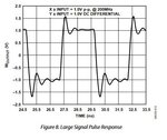
At the moment I am looking at the following switch;


I can’t find a faster analog switch, do you think I can find one? Am I looking in the wrong places?

thanks
 

Hi,

Definitely a fast analog switch.
But if it works depends on your expectation and on your schematic

Example:
If you connect the switch in series with your signal and feed the signal to a scope probe...maybe you see just the input signal (with some distortion).
Why: the switch is an SPST only, thus it switches ON and OPEN (not: ON and ZERO!), but the voltage of an OPEN node is not defined. Now it depends on stray currents and stray capacitance how the voltage will behave.

So show us your circuit, your test conditions, your expectations (at least a sketch of a timing diagram).... if you need more detailed assistance.
Do simple timing calculations on your own to get a clue of what you can expect. We won't do this for you ... but if you show us we will verify them.

Klaus
 

Hi Dana - thats the part I have already selected.

@KlausST thanks for the feedback....

I am basically down mixing an input signal which is known (lets say a 70MHz sinusoid) down to 20kHz and filtering out all components above 20kHz, in this case i use a 100kHz low pass up stream.

I will toggle the switch on and off @ Fin - 20kHz.

There is an ADA4817 up stream feeding this circuit - straight from the output of the op amp into this switch.

See attached a basic schematic showing the switch and the upstream low pass filter.

@70MHz I have a 14ns time period, leading to a 7ns "off time" and 7ns "on time" approximately.

Given that the Ton and Toff are up to 6.9ns.... I think this switch will struggle... Or have I misinterpreted this? This is my first time working with such a switch.

I was considering putting a resistor between the output of the switch and ground to "short" the signal to ground when the switch opens and discharge any stray capacitance... But not sure if this is necessary or at the moment how it affects the upstream filter - i need to analyze this.
 

Attachments

  • downmixer.JPG
    downmixer.JPG
    31.7 KB · Views: 90

Hi,

A symmetric ton / toff delay won't hurt. Then the output is just shifted.
A non symmetric delay will still downmixing but the output voltage not that predictable.

But what worries me is the capacitor across the switch combined with the high load impedance I doubt it it will work satisfactory.
To be true I have no experience with this type of downmixing.

It seems like a simulator circuit .... what does the simulation say?

Klaus
 
Why not just use a mixer chip, like a simple hard
switched FET-quad? The LO input pins can be
driven either sine (capacitor-blocked) or square
wave. Lots of options from Mini-Circuits, and the
many RF IC vendors.
 
Why not just use a mixer chip, like a simple hard
switched FET-quad? The LO input pins can be
driven either sine (capacitor-blocked) or square
wave. Lots of options from Mini-Circuits, and the
many RF IC vendors.

Oh my, you have just introduced me to a world of options! Thank you...

I need to look into this a lot further, as on first look it seems these are all transformer coupled - I am worried about linearity.

My IF frequency will always be 20kHz, with F1 and F2 in the range of 1MHz to around 70MHz....

Thanks a lot @dick_freebird
--- Updated ---

Hi,

A symmetric ton / toff delay won't hurt. Then the output is just shifted.
A non symmetric delay will still downmixing but the output voltage not that predictable.

But what worries me is the capacitor across the switch combined with the high load impedance I doubt it it will work satisfactory.
To be true I have no experience with this type of downmixing.

It seems like a simulator circuit .... what does the simulation say?

Klaus

The cap was to just simulat the capacitance across that analog switch.

The simulation seems good, but I am just not happy about the rise/fall time - I haven't analysed it in depth yet but feel that the rise/fall isn't quick enough...

Maybe a dedicated mixer is the way to go, hopefully i can find one covering <100MHz.
 

You may find some of the mixer chips assert a
lower frequency limit, but this isn't to be taken
as fact; sometimes it's just how low they have
characterized a part meant for the cell phone
market. Bare FET-quads have no lower limit,
per se. A chip with integrated blocking caps,
might. Low frequencies might need a balun
that's way bigger than the active device I
expect, if you need to get back to a single
ended signal (FET-quads are meant for
differential LO and signal paths).
 

    Smillsey

    Points: 2
    Helpful Answer Positive Rating
What about the concept of a multiplier? Such as this one... I will be using a square wave clock signal at Fin - 20kHz and can feed that into the multiplier....

What do you think?

--- Updated ---

I could actually generate a sinusoid from a DAC and multiply the incoming signal by that @ Fin -20kHz.
--- Updated ---

The pulse response is extremely good, unless I am missing something I think this would do the trick...
 

Attachments

  • pulse_response.JPG
    pulse_response.JPG
    32 KB · Views: 71
Last edited:

For anybody reading this in the future, I have been researching analog switches as initially i was confused with what Ton and Toff actually respresented - i interpreted it incorrectly to mean rise and fall time of the analog signal which is wrong.

All Ton and Toff represent is propagation delay - not an issue for my application.

An anlog switch is therefore back onto the drawing board as an option :)
 

Status
Not open for further replies.

Similar threads

Part and Inventory Search

Welcome to EDABoard.com

Sponsor

Back
Top