Continue to Site

Welcome to EDAboard.com

Welcome to our site! EDAboard.com is an international Electronics Discussion Forum focused on EDA software, circuits, schematics, books, theory, papers, asic, pld, 8051, DSP, Network, RF, Analog Design, PCB, Service Manuals... and a whole lot more! To participate you need to register. Registration is free. Click here to register now.

9000 watt modified sine wave inverter

Status
Not open for further replies.

abdoalghareeb

Member level 5
Joined
Feb 5, 2010
Messages
83
Helped
1
Reputation
2
Reaction score
1
Trophy points
1,288
Activity points
1,974
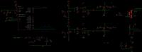
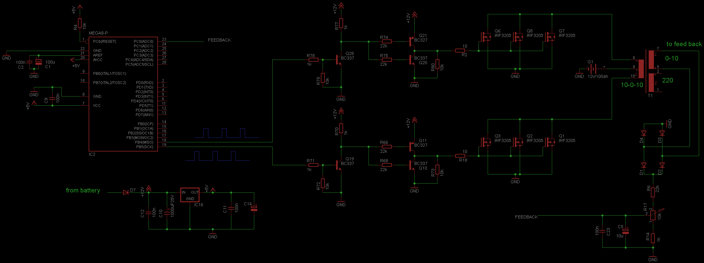
One year ago I have built 500 watt modified sine wave inverter.
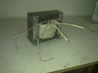
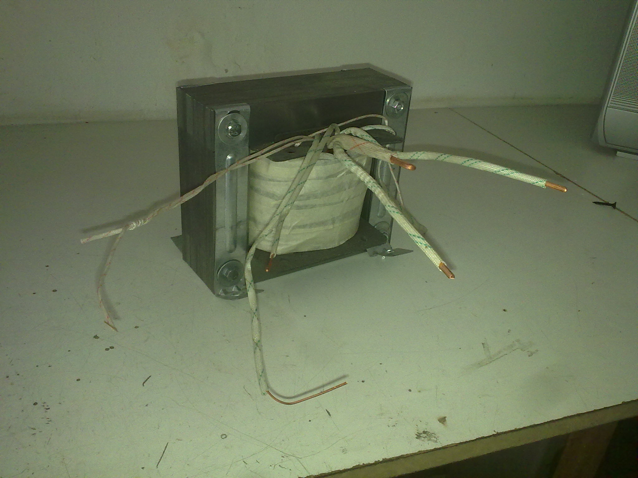
I used iron core transformer (10-0-10 on primary,0-220 on secondary ),avr microcontroller , irfp064 mosfet transistor and 12v/100Ah lead acid battery .this is the schematic of my circuit and the transformer:


Now I want to build 9000 watt inverter . this inverter will drive 9 sewing machines , the specifications of each motor is (400 watt,two phase,2.9 amp and 2850 rpm).

Is my last design suitable for this power inverter ?
What is your advises ?
 

9 kW @12V = 660A, this looks like a severe problem. I think you must reconfigure your battery supply to 50 V. This would give you 9 KW/50 = 180 A still a large number but doable.
If each sewing machine takes 400 W, then 9 would take 3.6 KW, which is a lot less then 9 KW. In either case I think that you need to wind several primaries to split the current paths, else you will need to wind it with extremely thick copper bar.
If you duplicate the drivers and output stages and drive a separate primary from each one on a common transformer core. A "booster" on the output of the micro might be useful to increase its fan out.
Frank
 

First - check the price of the battery you need. It needs a rating of AT LEAST 750 Amps per hour of use. So if you use it 10 hours per day it should be 12V 7500AH.

Brian.
 

What do you mean by wind several primaries , how its work ?
What is the booster circuit I need?
 

Your schematic had its parts too far apart so it would not fit on my wide screen, so I cropped it.
Your schematic was a negative with poor contrast so I inverted it and increased its contrast. Now with a normal white background it can be seen:
 

Attachments

  • 500W mod sinewave inverter.png
    500W mod sinewave inverter.png
    110.2 KB · Views: 172

1. 9000/12 = 750 A not 660. As your drive pulses are on for 20% of the time, current flows for 40% of time, so you need a current of 2.5 the above numbers.
2. Copy the pin 8,9,10 arrangement on to the same core and connect it to its own output and driver stage.
Frank
 

Going from 500W to 9000W is a BIG change.

To illustrate that, look at the price per watt for commercial inverters for 500W and 5000W models.

Is the 400Watt for the sewing machines the average or peak current? I suspect the average. The peak would be much higher. Most sewing is stop-and-go - when the machine is engaged, there is a current inrush.

Another consideration is what if your single large inverter fails? Then all the sewing machines stop?

I think it would be better to have several 'smaller' inverters which are easier to construct, and avoid a single point of failure.
 

I simply take for granted that there is no war in my country and the electricity (and food and water and fuel and education and medical and entertainment and .....) keep on coming. I have never needed an inverter for anything. Things are very different over there.
 

equal in syria 10 100 !!!!!!!!!!!!!!!!!!!!
 

I think your biggest problem is that motors require a sinusoidal waveform and not a rectangular one....
 

Status
Not open for further replies.

Part and Inventory Search

Welcome to EDABoard.com

Sponsor

Back
Top