Continue to Site

Welcome to EDAboard.com

Welcome to our site! EDAboard.com is an international Electronics Discussion Forum focused on EDA software, circuits, schematics, books, theory, papers, asic, pld, 8051, DSP, Network, RF, Analog Design, PCB, Service Manuals... and a whole lot more! To participate you need to register. Registration is free. Click here to register now.

[SOLVED] 555 Timer Monostable feedback

Status
Not open for further replies.

walumbe

Junior Member level 2
Joined
Oct 15, 2013
Messages
20
Helped
0
Reputation
0
Reaction score
0
Trophy points
1
Activity points
174
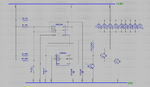
I have a circuit with two 555Timers and a dark detector circuit that turns on a LED board. The first timer controls the amount of time the circuit stays on (3 minutes) and is tied to a second timer that turns on when triggered by a tilt switch. Both this timers stay on for 3 minutes or until the switch is triggered again to keep the LED board on.

I have built this circuit on a breadboard and it works fine, but when I build it using the same value components on a PCB board the LED board flickers as the tilt switch is activated. Could this be an issue to do with grounding or is it a frequency issue with the timer? I'm new to PCB design so I think it is something to do with the PCB board design and its grounding.

- - - Updated - - -

Here's my shematic
SCHEMATIC.png

- - - Updated - - -

Here's my shematic
SCHEMATIC.png
 

The fact that this works fine on the breadboard and not on the PCB would point to an error on your PCB.
 

Hi Vcc of 555 IC is missing, the resolutions is too low to check the circuit.........
 

Check the supply voltage between pin 8 and pin1 of your NE555 as venkadesh said..
 

Thanks.
Sorry, I uploaded an older version of my schematic. Here the updated one with better resolution.
 

Attachments

  • SCHEMATIC.png
    SCHEMATIC.png
    170.2 KB · Views: 72

Can you explain this circuit? I've probably got it wrong, but it LOOKS like when the switch closes, both 555 outputs go high. They will stay high until the top one goes low, resetting the bottom one. In other words, the output of the bottom is the same as the top.

Actually, to further confuse me, you've got a 100K pullup on the bottom trigger and a 10K on the top trigger. BUT THEY'RE BOTH CONNECTED TOGETHER!
 

The top is a timer circuit that stays high for a period of time. Its output resets the second timer that is triggered by a tilt switch tied to ground. The output of the 2nd timer controls a phototransistor that is part of a dark detecting circuit which turns on the LED board in darkness. To summarize, the LEDs will turn on only in the dark and the tilt switch is activated and should stay on for a period of time (2-5 min).
 

The bottom one is not a timer, it is imply a latch that gets set by the trigger (switch closure) and reset by the top timer. The outputs are the same (disregarding propagation delays).
 
Barry,

Yes the bottom 555 Timer is a latch that is set by the tilt switch and reset by the timer. This setup works perfectly on the breadboard, but for some reason on the PCB board the tilt switch keeps re-triggering and in turn causes the LED board to flicker.
 

Your tilt switch is resetting the top timer. I don't think you need the trigger and reset connected together; tie reset high. On second thought, you definitely don't want trigger and reset tied together--they're trying to do opposite things!!!
 
Thanks Barry. I will try that out and let you know my findings.
 

Barry, I did as you suggested and the latch works great. But the timer has to run through a complete cycle before it can be triggered again. I initially tied the timer's reset pin to the switch so that it resets the counter each time the switch is activated.
 

Hi I think you can do the same with a single 555. can i explain if you press the switch the LED has to glow if no light and if the switch is opened the LEDs shd off after 3 min...
but whenever the light comes the LED offs...

Shall i explain a most possible cause of your blinking problem, It was the photo transistor near the LED or exposed to LED.... when darkness comes LED glows, when LED glows darkness goes and LED offs this process continues...
 

Barry, I did as you suggested and the latch works great. But the timer has to run through a complete cycle before it can be triggered again. I initially tied the timer's reset pin to the switch so that it resets the counter each time the switch is activated.


You can't have it both ways: RESET forces Q low, TRIGGER forces it high. Apparently what you really want is a RETRIGGERABLE one-shot, which the 555 is not. And, once again, that latch is redundant-it's output is identical to the top timer.
 
Vankadesh_M, I have tested the circuit and the the flickering is not caused by the phototransistor as it is not exposed to the LED board in the housing.

Barry, I see your point about the redundancy of the latch. Would you happen to know of a RETRIGGERABLE one-shot IC that I can look at?
 

Look at a CD14538, 74HC4538. Dual, retriggerable one-shot. Cheap and plentiful.
 

Status
Not open for further replies.

Similar threads

Part and Inventory Search

Welcome to EDABoard.com

Sponsor

Back
Top