azadfalah
Full Member level 2
Hello friends
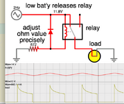
Can the part mentioned in the circuit below be modeled with the help of one or two BJTs?
The culprit of the question is, can the mentioned negative feedback operation be implemented in a simpler way but with the same stability?

We assume that the reference voltage is 0.7
I found a close circuit but not sure if it is as stable

Thank
Can the part mentioned in the circuit below be modeled with the help of one or two BJTs?
The culprit of the question is, can the mentioned negative feedback operation be implemented in a simpler way but with the same stability?
We assume that the reference voltage is 0.7
I found a close circuit but not sure if it is as stable
Thank