yohan99
Newbie
Hello!
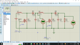
I am a final-year engineering student. For my final year project, I am supposed to design and implement a transformerless inverter with 230V output,50Hz, and 1KW power. My plan is to boost 12vdc into 320vdc via a boost converter and convert 320vdc into 230vac via an h bridge with 4 MOSFETs. I got a working simulation for the boost converter, but its physical implementation does not work. 4.2mF and 1mF capacitors are 50v rated. For inductors, I am using radial power inductors. For the 12V supply currently, I am using a general power supply at the campus lab.
Two PWM signals with 20kHz are given to two MOSFETs. Currently, I am trying to get PWM signals from the signal generator in the lab. (but I am planning to use a PWM generator (pulse generator link ) )
I attached a screenshot of the circuit diagram of the boost converter. I searched on the internet for a better solution but unfortunately, there were no better solutions. Therefore I am looking for help from an expert on this issue.
Thank you
Datasheets links:
IRF510