Continue to Site

Welcome to EDAboard.com

Welcome to our site! EDAboard.com is an international Electronics Discussion Forum focused on EDA software, circuits, schematics, books, theory, papers, asic, pld, 8051, DSP, Network, RF, Analog Design, PCB, Service Manuals... and a whole lot more! To participate you need to register. Registration is free. Click here to register now.

1 amper half wave constant current source

Status
Not open for further replies.
Pls advise. What is the purpose?
What is the real source & load impedance ?
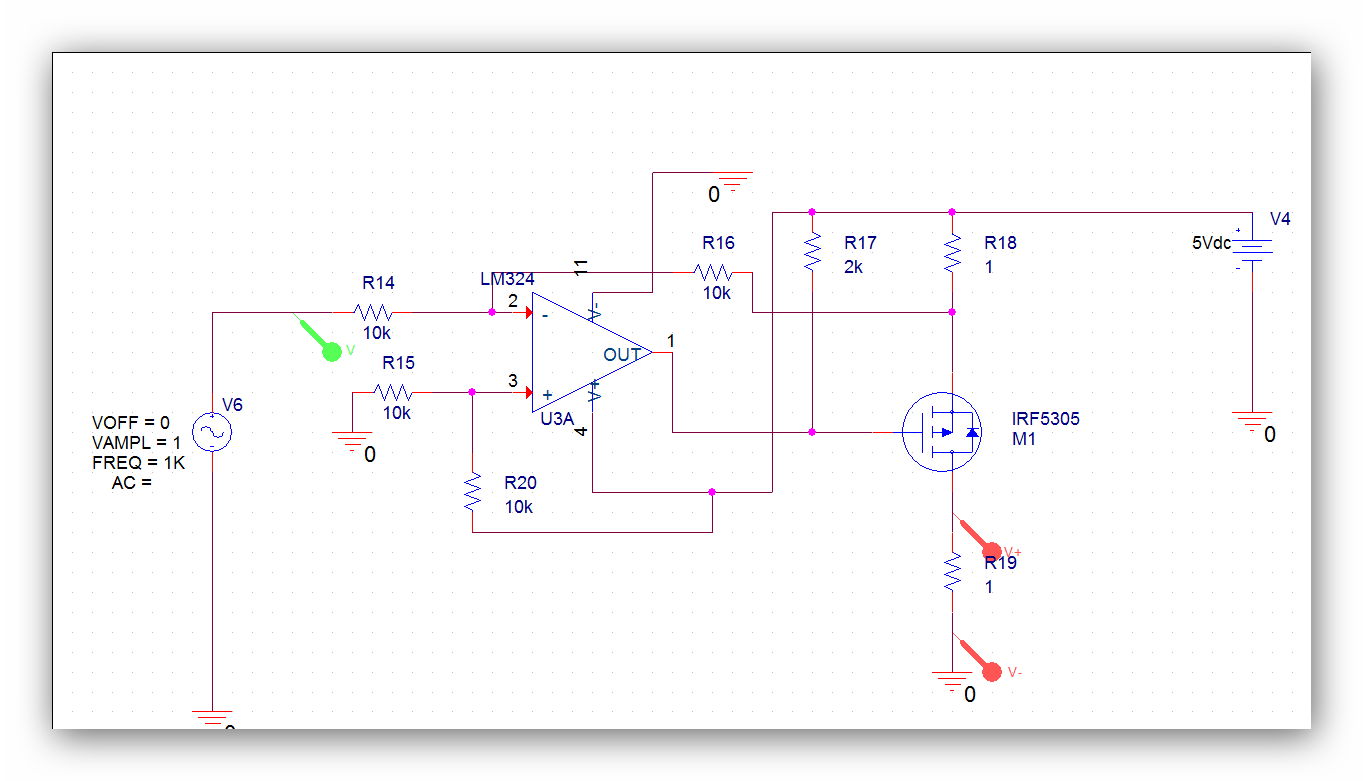
In Fact the load is Lead-acid Battery . I want to measure Internal Resistance Of battery and SOC & Soh Did You have better solution , i inject Ac current to battery and measure Ac Voltage from that then Ac Voltage/Ac Current is : Internal Resistant .
 

Ok , that makes more sense. There are many acceptable methods and some IEC 1000Hz standard... Using an AC signal over DC.

I prefer pulsed current test from 0.1A to 1.1A for light batteries and 1 to 11A for heavy batteries to the change in current gives ESR in voltage with a moving decimal point and always has a DC component.

Beware that the peak-peak AC voltage is converted to RMS in DMM's based on a sine , and not a square wave, which have different correction factors.

You can use a sine wave with a DC offset to stabilize the chemistry that raises the no load float voltage. Thus for a 1A pp CC with a 0.6Adc offset the current would be .1 to 1.1A which could be done with any closed loop circuit and a 50mV current shunt for intended current measurement range.

Since ESR drops with rising cell temp, it follows that higher current tests or repetitive tests will reduce Tests may reduce the low current ESR.


ESR also drops with reduction in Sulphation due to <50ns pulses such as 5A at low duty cycle. It also raises specific gravity. I tested the original invention on Motive Power batteries using a tiny pulse box triggered to activate with the charger voltage present. They really work. Here's another design that followed .
 
Below is the sim of a current source with a differential DC input as compared to the single-ended AC coupled input of my design in post #7. Again it shows a 1A peak current for loads of 0.1Ω, 0.5Ω, and 1Ω It also is able to use a common LM324 or LM358 single-supply op amp. The sim has the lower input (In-) grounded but it can be used to accept a differential input in conjunction with the In+ input, or used as a inverting input with the In+ input grounded.

Note that R1 should be a 1W resistor.

View attachment 109588

I got an acceptable result, But i have a Big Problem if i add a elec-cap after mosfet that is cases Preventing the ac signal
the capacitor is fully charged when The half-wave signal passes through.
Do you have a solution to this issue?
I should add that capacitor . and I Can not Delete that.
Ashampoo_Snap_2014_09_28_16h46m09s_003_.jpg

Ashampoo_Snap_2014_09_28_16h46m24s_004_.jpg


After Add That Capacitor I Have a this ??

Ashampoo_Snap_2014_09_28_17h14m47s_005_.jpg

Ashampoo_Snap_2014_09_28_17h15m11s_006_nima1_dat_active_.jpg
 
Last edited:

I got an acceptable result, But i have a Big Problem if i add a elec-cap after mosfet that is cases Preventing the ac signal
the capacitor is fully charged when The half-wave signal passes through.
Do you have a solution to this issue?
Yes, you can't use a capacitor for that circuit since the current-source is unipolar. One solution is to use a power supply greater than the battery voltage, say 15-20V. That way the output can go above 12V and you can direct couple the MOSFET current output to the battery.
 
I am not sure if you understood my suggestions, of Full wave AC with a DC offset. Normally the sine current source is a small signal with a larger DC current in measuring ESR.

Also a battery has capacitance of many Farads., but you are only measuring the series resistance..
 
there is no way to flow Half Wave From Electrolytic capacitor ????
Not with the circuit I posted!!!
But with that circuit you don't need a capacitor so what's your concern?
 
Not with the circuit I posted!!!
But with that circuit you don't need a capacitor so what's your concern?

I Explain my problem the Rload is a battery that is grounded with our circuit.if we do not put coupling capacitor that is shorted .
And Dc current flows to Mosfet and other part .?? we need block dc after Rload(battery )with Coupling capacitor .
 

In order to provide 1A constant current from a 1Vp 1kHz source, the voltage source must have an ideal 0Ω impedance and the load must be low enough resistance to demand it.

Generally with such low voltages , you have no margin to maintain such current. In any case the source resistance must be much lower than the load to supply enough voltage to deliver 1A

If all you want is a 1A current limiter, this is not constant for a sine voltage.

Pls advise. What is the purpose?
What is the real source & load impedance ?


You may want to rethink your design. This design shunts the load between 12V & 5V instead of 12V and ground. If might want to use a 0.1Ohm current shunt to ground and have the Mosfet as an active load between 12V and shunt to gnd. The OpAmp can run off the 12V and accuracy is then dependant on R values/ratios and not 5V.


Also change the V+ bias >Vac.pk to have a DC offset instead of none.

Don't AC couple to battery, the cap. is way too small anyways compared to capacitance and ESR of battery. Expect to amplify the AC voltage to read ESR in mOhm.


The 5V is not required. The DMM or ADC will have a precision reference for measuring voltage in mV or ESR in mOhm .

Make sure Idc>=Iac
 
Its good idea but in this project I am not allowed to use shunt ,
i amplify the ac voltage by ad620 with gain 100 or gain 500 (this is no matter)
but the big problem was not solved for dc blocking ?
you say me don't couple ac to battery with capacitor .
But tell me, how I Can block DC voltage without Capacitor
thanks again
Nima
 

You must load the battery with Idc to remove the memory effect after charging. You superimpose the AC direct coupled then remove the DC in the voltmeter side with a small nonpolar cap into high impedances.

The 1 Ohm is your current shunt, but misdirected to +5.


It is better to shunt to gnd and sense either high or low side for current feedback while voltage sensing across battery.
 
I Explain my problem the Rload is a battery that is grounded with our circuit.if we do not put coupling capacitor that is shorted .
And Dc current flows to Mosfet and other part .?? we need block dc after Rload(battery )with Coupling capacitor .
What's with the red letters? :-?

My circuit is a current source with a high dynamic output impedance. It's output current is independent of the output (battery) voltage. It's output current is solely determined by the input control voltage. So there is no current that needs blocking with a capacitor.

Is there any part of that which you don't understand?
 
My circuit is a current source with a high dynamic output impedance. It's output current is independent of the output (battery) voltage. It's output current is solely determined by the input control voltage. So there is no current that needs blocking with a capacitor.

That's the exact solution to generate an unipolar current.

You also mentioned an essential point in post #24. Ther current source supply must be sufficiently greater than the battery voltage. If problems during power-up etc. are expected, a series diode can be used.

Red text is in fact against forum rules.
 
Thinking some more about the battery test, you don't need a high side current source. You can also use the simpler low-side current source as shown below. It uses an N-MOSFET which is generally cheaper and easier to find than the P-MOSFET of the high-side source.

The main functional difference is that with this circuit the current pulse direction is going out of the battery rather then into the battery, but that should make no difference for the measurement of the battery's internal resistance.

Edit: And a big plus is that this circuit does not require a separate power supply as the high side source does. The battery under test powers the circuit.

Note that the average power dissipated in the MOSFET is about 3.8W so it will need to be on a heatsink. That's true for the high-side source also.

Current Source.gif
 
Last edited:
nima_1981:
the last circuit that Crutschow posted is exactly what you need.

The only other thing that you require (if you don't have access to an oscilloscope) is an AC-coupled differential amplifier to monitor the minute changes in battery voltage. You can monitor the output of said amplifier with your DMM, but unless it is a true RMS reading type, you'll have to build your own.
 

.......................
The only other thing that you require (if you don't have access to an oscilloscope) is an AC-coupled differential amplifier to monitor the minute changes in battery voltage. You can monitor the output of said amplifier with your DMM, but unless it is a true RMS reading type, you'll have to build your own.
If the amp is AC coupled it doesn't need to be differential.
 

hi my friend.
I need half wave constant current source for grounded load
Resistance of load is under 1 ohm
my oscillator output voltage is near 2 Volt peek to peek
any one have idea for that ,
Thanks

I still don't understand why you wish to test lead acid batteries with a half sine 1kHz wave at 1A , when this is not how it is done by IEC standards. Look at how one of the best battery testers specs their product. This sine wave is not rectified thus has DC offset. .

image.jpg

Others use swept frequency or Matrix testing for ESR, which is even more accurate for predicting SOC with battery profiles.

Mallory on the other hand for dry cells use pulse method with a small offset like 1-11 or 10-110mA
 

Status
Not open for further replies.

Part and Inventory Search

Welcome to EDABoard.com

Sponsor

Back
Top