Continue to Site

Welcome to EDAboard.com

Welcome to our site! EDAboard.com is an international Electronics Discussion Forum focused on EDA software, circuits, schematics, books, theory, papers, asic, pld, 8051, DSP, Network, RF, Analog Design, PCB, Service Manuals... and a whole lot more! To participate you need to register. Registration is free. Click here to register now.

[SOLVED] Level shifting in OPAMP and HE100T01 interfacing problem

Status
Not open for further replies.

archusvijay1

Member level 3
Joined
Mar 12, 2014
Messages
61
Helped
0
Reputation
0
Reaction score
0
Trophy points
6
Activity points
553
Hi,

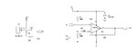
I want to measure current of 0-50A. For that, in my application I am using HE100T01 hall effect sensor which can measure current from -100A to +100A(depending on the direction of flow it gives -ve and +ve values).
The Hall effect sensor gives a current output of -50mA to +50mA. Since my micro controller ADC can't measure negative voltage, I tried level shifting the sensor output to positive region using the circuit which is attached. But the negative voltage is not properly clamping to the +2.5V offset. Can anyone please help me to identify the problem and also give any alternate circuitry to convert the sensor output which can be measured using a micro controller ADC?

Please find the datasheet for the Hall effect sensor and attached schematic.
**broken link removed**

Looking forward for earlier responses.

Regards,
Archu
 

Attachments

  • 2_1_HE100T01-05.pdf
    347 KB · Views: 92
  • HE100_OPAMP.JPG
    HE100_OPAMP.JPG
    32.5 KB · Views: 60

Is the 324 wired so the output signal goes high when the input is above 50% supply? That's what I understand from the schematic. I don't use op amps much, but maybe the other way round is what you mean? - Non-inverting to 100k divider and input to the inverting input, so when input below (not above) 2.5V, output goes high.

Would it help to use the -15V you have stepped down to -5V somehow and power the 324 from a dual supply?

This thread has a similar topic, if it helps:

https://www.edaboard.com/threads/347139/
 

The circuit does in fact a negative instead of the intended positive level shifting. Quite obviously, a single supply non-inverting amplifier can't process the negative input voltages corresponding to negative currents.

A simple way to achieve a positive level shift is to use two resistors and a reference voltage. No OP needed.
 

Hi,

Do you want to measure AC only,
Or a you interested in DC also.

If AC only, then a capacitor and two resistors do the job...without opamp.

****
It is for an ADC input. If you want some precision I don't recommend to use VCC as ref.
In either way use half of the voltage, made with two identical resistors, to shift the voltage.

I recommend to use a modified difference amplifier opamp circuit.
Sensor via resistor to In+ of opamp.
Gnd via resistor to In- input. (For best performance add the same resistor as the sensor burden resistor in series)
Feedback from output via resistor to In-.
Now the modification: from In+, two identical resistors, each twice the value of the feedback resitor, one to GND the other to VREF of the ADC.

Klaus
 

The circuit does in fact a negative instead of the intended positive level shifting. Quite obviously, a single supply non-inverting amplifier can't process the negative input voltages corresponding to negative currents.

A simple way to achieve a positive level shift is to use two resistors and a reference voltage. No OP needed.

Hi,
thanks for the quick response.
I tried this one, but fails, i think the output voltage is very low across the burden resistor.
reference voltage is created by a voltage divider 10K across the vcc and ground. Output voltage coming from the burden resistor is connected to the reference point through 1k resistor.

is there anything wrong in this setup?

Thanks,
Best regards,

- - - Updated - - -

Hi,

Thank you for the response.

we want to measure dc only.and it is inputted for adc. But I cant use Neg vref because this controller doesn't support it. The reference voltage which we are using is VDD of controller.
Now the modification: from In+, two identical resistors, each twice the value of the feedback resitor, one to GND the other to VREF of the ADC
According to the datasheet of HE100 the maximum value of burden resistor is 33 ohms and we are using 30E as resistor. Is this the same resistor value you suggested to add in series?
For connectiing do we need to level shift the sensor output before giving it to OPAMP?

Appreciate early response.

Thanks and regards
 

Hi,

If you use 30 Ohms, then add 30 Ohms also to negative input.

No need for negative VRef.
No need for extra level shift. It is made with the two resistors to Vcc and gnd, connected to In+.

Klaus
 

Hi,

If you use 30 Ohms, then add 30 Ohms also to negative input.

No need for negative VRef.
No need for extra level shift. It is made with the two resistors to Vcc and gnd, connected to In+.

Klaus

Hi,
you are suggesting that a basic non inverting circuit with sensor input to IN+ via 30 ohm resistor with a voltage divider (10K). and a grounding resistor 30 ohm to IN- to Ground and a feedback resistor (30 ohm) for unity gain.
am i write?
 

Status
Not open for further replies.

Similar threads

Part and Inventory Search

Welcome to EDABoard.com

Sponsor

Back
Top