nz_tech
Newbie level 2
I would like to modify this charger to run from a DC source.
I could just just run it from an inverter but that seems like a lot of wasted energy in conversion
12vdc > 240vac > Charger
Also would like to keep it all in the current case if possible.
In the old days of transformer based chargers it was easy enough, find the rectified voltage DC voltage.
Insert new supply here.")
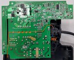
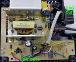
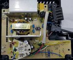
We have a dual battery charger from milwauke.
Multi voltage charger M12-18C
PCB images attached.
Looks like a dual voltage output.
There is 2 opto's to provide some feedback between the primary and secondary side of the system.
The charging smarts is provided in battery so all the charger needs to do is supply the voltage the batteries needs for charging itself.
Cut off on any error conditions from the battery.
The plan was remove the primary side.
Supply the required DC voltages to the secondary side using off the shelf DC-DC converters.
Figure out what I need to do with the two opto feedback IOs.
Hopefully it is just a straight on/off and not pwm or something more complicated.
Questions before I break the scope out.
Is this likely to work?
Any potential issues I might have missed?
Thanks in advance
I could just just run it from an inverter but that seems like a lot of wasted energy in conversion
12vdc > 240vac > Charger
Also would like to keep it all in the current case if possible.
In the old days of transformer based chargers it was easy enough, find the rectified voltage DC voltage.
Insert new supply here.
We have a dual battery charger from milwauke.
Multi voltage charger M12-18C
PCB images attached.
Looks like a dual voltage output.
There is 2 opto's to provide some feedback between the primary and secondary side of the system.
The charging smarts is provided in battery so all the charger needs to do is supply the voltage the batteries needs for charging itself.
Cut off on any error conditions from the battery.
The plan was remove the primary side.
Supply the required DC voltages to the secondary side using off the shelf DC-DC converters.
Figure out what I need to do with the two opto feedback IOs.
Hopefully it is just a straight on/off and not pwm or something more complicated.
Questions before I break the scope out.
Is this likely to work?
Any potential issues I might have missed?
Thanks in advance